Steering gear gap adjustment mechanism

A gap adjustment mechanism and steering gear technology, which is applied to mechanical steering gears, mechanical equipment, portable lifting devices, etc., can solve problems such as inability to perform gap compensation, increased space occupied by the coil spring 4, and insignificant improvement in abnormal noise, etc.

Inactive Publication Date: 2017-10-03
CHERY AUTOMOBILE CO LTD
View PDF4 Cites 9 Cited by
  • Summary
  • Abstract
  • Description
  • Claims
  • Application Information

AI Technical Summary

Problems solved by technology

At present, the adjustment structure adopted by the gear shaft and rack type steering gear mainly solves the problem of gear shaft teeth by adjusting the stiffness of the coil spring 4 or adjusting the compression amount of the coil spring 4 to change the pressing force applied to the pressure block 3 and other parameters. However, the adjustment of the spring parameters will inevitably change the parameters such as the diameter and length of the coil spring 4. If the parameters such as the diameter or length of the coil spring 4 change little, the pressure of the coil spring 4 will The pressing force exerted by block 3 does not change much, and the improvement of the abnormal noise will not be obvious, but if the diameter or length of the coil spring 4 changes greatly, although the pressing force will increase, the space occupied by the coil spring 4 will also increase. This is not conducive to the arrangement of the pinion and rack steering gear on the vehicle
Once there is wear between the parts and the fit gap increases, this structure cannot perform gap compensation in the future, and the abnormal noise will only become more and more obvious

Method used


Image

  • Steering gear gap adjustment mechanism
  • Steering gear gap adjustment mechanism
  • Steering gear gap adjustment mechanism

Examples


Embodiment Construction

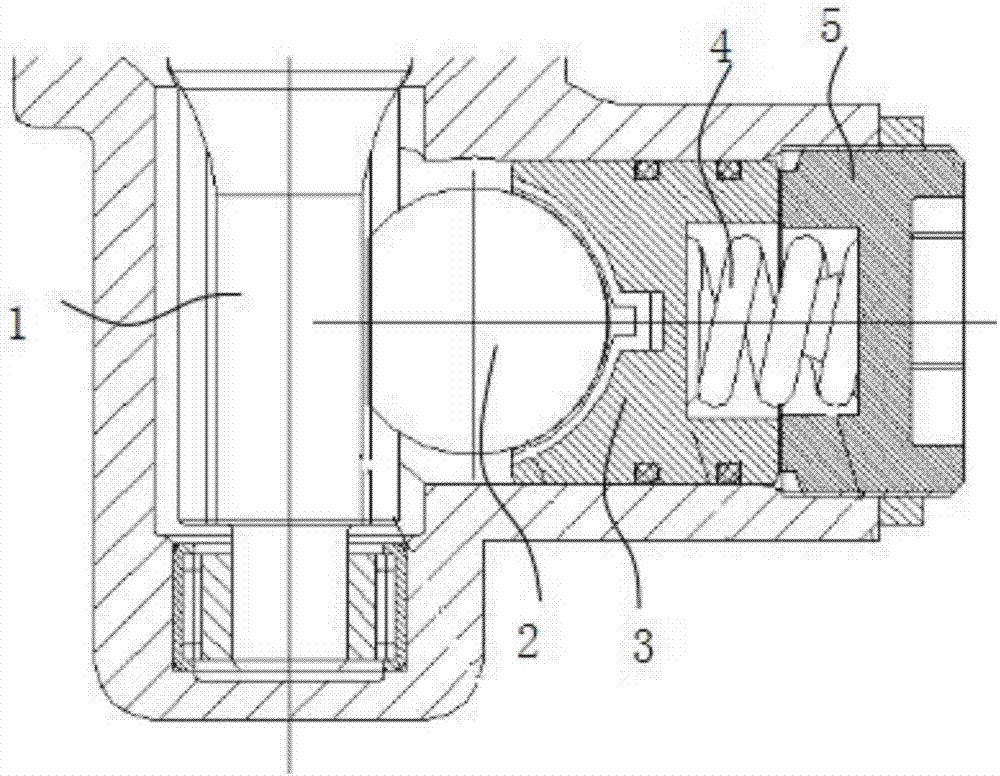
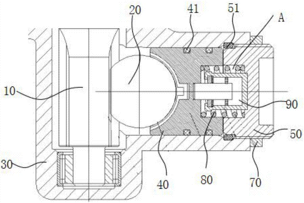
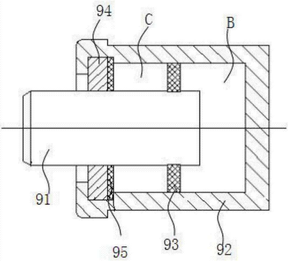
[0010] Such as figure 2 As shown, a steering gear gap adjustment mechanism includes a steering input gear shaft 10 and a rack 20 that mesh with each other, and a pressure block 40 that is in contact with the rack 20 is arranged in the steering gear housing 30 on one side of the rack 20 , the port of the steering gear housing 30 is provided with an adjusting screw plug 50 that limits the position of the briquetting block 40 , the adjusting screw plug 50 is sleeved with a lock nut 70 for locking its position, and the briquetting block 40 and the adjusting screw plug 50 are provided with There are recesses with opposite openings, and the two recesses are butted to form a chamber A. A coil spring 80 is arranged in the chamber A. One end of the coil spring 80 is abutted against the pressure block 40, and the other end is abutted against the adjusting screw plug 50. The chamber A A damping unit 90 is also provided inside, the end of the piston rod 91 of the damping unit 90 abuts ag...


PUM


Abstract

The invention aims to provide a steering gear gap adjustment mechanism which can effectively reduce abrasion among parts and is small in occupied space. The steering gear gap adjustment mechanism comprises a steering input gear shaft and a rack which are mutually engaged; a pressing block and an adjustment screw plug are provided with concave parts with openings being opposite; the two concave parts are in butt joint to constitute a chamber; the chamber is internally provided with a spiral spring; one end of the spiral spring abuts against the pressing block, and the other end of the spiral spring abuts against the adjustment screw plug; the chamber is further internally provided with a damping unit; the end of a piston rod of the damping unit abuts against the pressing block; and the pressure in a valve cavity of the damping unit drives the piston rod to move towards the pressing block. When the rack overcomes resistance of the spiral spring and the pressing block and continues to move towards the adjustment screw plug, resistance generated by a mixture in the first valve cavity prevents the rack from continuing to move, thus the pressing block and the adjustment screw plug are made to make slow contact with each other through reaction force generated by compression of the spiral spring and compression of the damping unit to avoid impact of the pressing block and the adjustment screw plug with great energy, and therefore, the abnormal sound problem can be effectively solved.

Description

technical field [0001] The invention relates to the technical field of automobile steering systems, in particular to a steering clearance adjustment mechanism. Background technique [0002] With the development of the automobile market, people have higher and higher requirements for the comfort of passenger cars, and they are also more and more sensitive to the abnormal noise generated when the vehicle changes direction or goes over a bumpy road. The rack and pinion steering gear with tie rod assembly is an important component of the car. With the long-term driving of the car, the parts of the steering gear will wear out due to relative movement, and the gap between the parts will also Then it becomes larger, so it is easy to produce abnormal noise, and even reduce the performance of the steering system, which affects the performance of the vehicle and also affects the driving comfort of the driver. [0003] At present, the internal rack of the pinion and rack type steering...

Claims


Application Information

Patent Timeline
Patent Type & Authority Applications(China)
IPC IPC(8): B62D3/12F16H55/28
CPCB62D3/12F16H55/283F16H2055/281
Inventor 刘慧建裴洪莲章余发陈铭
Owner CHERY AUTOMOBILE CO LTD
Why Eureka
Try Eureka