Hanging type automobile spare wheel mounting device

A mounting device and a hanging technology, which is applied in the field of hanging-type car spare tire mounting devices, can solve problems such as the sinking structure of the tailgate, shaking of the spare tire, impact of the tailgate, etc. The effect of interior space

Active Publication Date: 2017-10-03
CHERY AUTOMOBILE CO LTD
7 Cites 3 Cited by

AI-Extracted Technical Summary

Problems solved by technology

However, if the spare tire is placed in the trunk, it is difficult to fix it during extreme driving, and the spare tire shakes; if the spare tire is hung on the tailgate, ...

Method used

1, by steel wire power transmission characteristic, utilize pre-tightening bolt, steel pipe, support, pressure head 13, spring and pressing plate 7, construct the pre-tightening device of a set of complete hanging type spare tire assembly, can effectively Ensure the preload of the hanging spare tire assembly, and the structure is simple and easy to install;
2. The two ends of the reinforcing plate are connected to the longitudinal beam by three-layer welding, which can transmit the larger moment that the body floor mounting point bears in the preloading process, so that the body floor mounting point can meet the strength performance requirements. In this way, the cracking of the body floor can be avoided, and the second is to ensure the smooth implementation of the lightweight of the car floor;
As shown in Fig. 1 to Fig. 8, the present invention provides a kind of hanging type automobile spare tire mounting device, comprises the spare tire reinforcement assembly that is connected with automobile floor, is used to make spare tire assembly hang on automobile The liftable suspension assembly under the floor and the preload assembly arranged on the spare wheel reinforcement assembly and used to control the suspension assembly to go up and down. The lifting of the suspension assembly is controlled by the pretension assembly, and then the spare tire assembly can be controlled to lift under the floor of the car, so as to realize the fixing of the spare tire assembly and the removal of the spare tire assembly. The car floor is a component that extends along the length of the car body at the bottom of the car body, and the spare tire assembly is hung under the car body, which will greatly save the interior space of the vehicle. Moreover, by rationally arranging the spare tire reinforcement assembly on the vehicle body, the installation point of the spare tire assembly vehicle body can meet the strength performance requirements.
Contrast accompanying drawing below, by the description of embodiment, the specific embodiment of the present invention is described in further detail, purpose is to help those skilled in the art to design of the present invention, t...

Abstract

The invention discloses a hanging type automobile spare wheel mounting device. The hanging type automobile spare wheel mounting device comprises a spare wheel strengthening assembly, a hanging assembly and a pretightening assembly, wherein the spare wheel strengthening assembly is connected with an automobile floor; the hanging assembly is used for enabling the spare wheel assembly to be hung under the automobile floor and can be lifted; and the pretightening assembly is arranged on the spare wheel strengthening assembly, and is used for controlling the hanging assembly to lift. The hanging type automobile spare wheel mounting device disclosed by the invention can greatly save the inner space of an automobile, is relatively simple in design structure, convenient to mount and good in generality, and can be used in most of SUV car models; the gravity center of the whole automobile body can be reduced, so that the passing capacity and the stability of the automobile are improved; and the spare wheel strengthening assembly is arranged, so that the strength requirement of automobile body mounting points can be met.

Application Domain

Spare wheel arrangements

Technology Topic

Automotive engineeringUltimate tensile strength +1

Image

  • Hanging type automobile spare wheel mounting device
  • Hanging type automobile spare wheel mounting device
  • Hanging type automobile spare wheel mounting device

Examples

  • Experimental program(1)

Example Embodiment

[0026] The following describes the specific implementation of the present invention in further detail through the description of the embodiments with reference to the accompanying drawings. The purpose is to help those skilled in the art have a more complete, accurate and in-depth understanding of the concept and technical solutions of the present invention, and Contribute to its implementation.
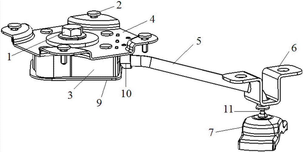
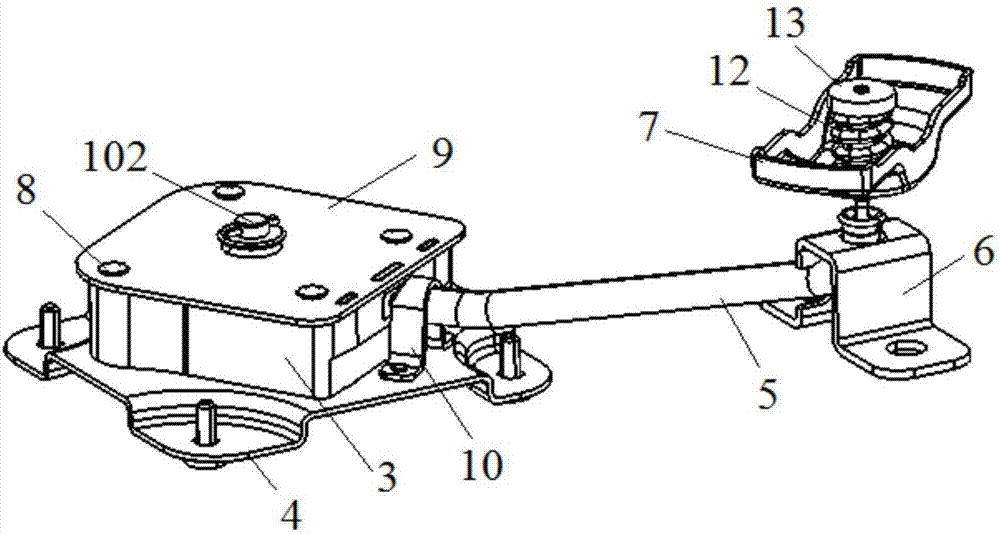
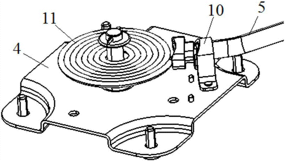
[0027] Such as Figure 1 to Figure 8 As shown, the present invention provides a hanging type automobile spare tire installation device, including a spare tire reinforcement assembly connected with the automobile floor, and a lifting assembly used to hang the spare tire assembly below the automobile floor. The pre-tension assembly is installed on the spare tire reinforcement assembly and used to control the lifting assembly of the suspension assembly. The lifting assembly is controlled by the pre-tensioning assembly, and then the spare tire assembly can be controlled to rise and fall under the car floor to realize the fixation of the spare tire assembly and the removal of the spare tire assembly. The car floor is a component extending from the bottom of the car body along the length of the car body. The spare tire assembly is suspended under the car body, which will greatly save the internal space of the vehicle. Moreover, the spare tire reinforcement assembly is reasonably arranged on the vehicle body, so that the body installation point of the spare tire assembly meets the strength performance requirements.
[0028] Specifically, such as Figure 5 with Image 6 As shown, the spare tire reinforcement assembly includes a longitudinal beam connected to the car floor and a reinforcing plate 14 connected to the longitudinal beam and the car floor. The longitudinal beams are located under the car floor and welded to the car floor. Two longitudinal beams are provided. The two longitudinal beams are the first longitudinal beam 16 and the second longitudinal beam 17, respectively. The first longitudinal beam 16 and the second longitudinal beam 17 are The first longitudinal beam 16 and the second longitudinal beam 17 are arranged in parallel and the length direction of the first longitudinal beam 16 and the second longitudinal beam 17 are parallel to the longitudinal direction of the automobile body (that is, the X direction of the automobile). The width direction (ie, the Y direction of the car) is arranged side by side, the first longitudinal beam 16 and the second longitudinal beam 17 are separated by a certain distance, and the length direction of the reinforcing plate 14 is parallel to the width direction of the car body.
[0029] Such as Figure 1 to Figure 3 As shown, the pre-tightening assembly includes a cable 11 connected to the hanging assembly, a storage box connected to the reinforcing plate 14 and used for accommodating the cable 11, and a pre-tensioning box that is screwed to the storage box and used to provide pre-tightening force. The tightening bolt 1, the first bracket 6 connected with the longitudinal beam and used to bear the X-direction and Y-direction pretensioning force, the second bracket 10 connected with the storage box, and the first bracket 6 and the second bracket 10 connected and allowed to pull The threading pipe 5 through which the cable 11 passes, and the pulling cable 11 is wound on the pre-tightening bolt 1. Through the rotation of the pre-tightening bolt 1, the cable 11 is wound on the pre-tightening bolt 1 or the cable 11 is released, thereby realizing the synchronous lifting of the suspension assembly and the spare tire assembly supported by the suspension assembly. The cable 11 is a steel wire, and the threading tube 5 is a steel pipe with two ends open and a hollow inside. The inside of the threading tube 5 is a steel wire channel for the cable 11 to pass through. The two ends of the cable 11 are passed through the threading tube 5 and pulled One end of the cable 11 is connected with the pre-tightening bolt 1, and the other end of the stay cable 11 is connected with the hanging assembly. The first bracket 6 is located above the hanging assembly. The first bracket 6, the threading pipe 5 and the second bracket 10 are located below the car floor. The first bracket 6 is mounted on the second longitudinal beam 17 by bolts. The first bracket 6 It is installed on the receiving box by bolts, one end of the threading tube 5 is fixedly connected to the first bracket 6 by welding, and the other end of the threading tube 5 is fixedly connected to the second bracket 10 by welding. The threading tube 5 is supported by the first bracket 6 and the second bracket 10, so that the inner cable 11 can stably transmit the pretension force according to the designated path. The axis of the pre-tightening bolt 1 is perpendicular to the X-direction and the Y-direction. There is an included angle between the length direction of the threading pipe 5 and the longitudinal direction of the second longitudinal beam 17, and the included angle is an acute angle. In the tight stage, due to the contact between the cable 11 and the threading tube 5, the internal force direction of the threading tube 5 changes, resulting in the generation of component forces in the X and Y directions. The first bracket 6 will bear larger X and Y directions. With pre-tightening force, the first bracket 6 is connected to the second longitudinal beam 17 by bolts, so that the installation point meets the strength performance requirements, and is safe and reliable. For different vehicle types, if the strength of the installation point of the first bracket 6 cannot meet the strength performance requirements, a reinforcing plate can be provided in the hollow inner cavity of the second longitudinal beam 17 to increase the strength.
[0030] Such as Figure 1 to Figure 3 As shown, the storage box is located below the reinforcing plate 14 and between the first longitudinal beam 16 and the second longitudinal beam 17. The storage box includes a connecting plate 4 connected to the reinforcing plate 14 and a wire box body 3 connected to the connecting plate 4 And the line box cover 9 connected to the line box body 3, the line box body 3 is located between the connecting plate 4 and the line box cover 9, and the line box body 3 is an annular structure with open ends, hollow inside and closed circumferentially, The wire box body 3 has a cavity for accommodating the cable 11 inside. The connecting plate 4 closes the opening at one end of the wire box body 3, and the connecting plate 4 is installed on the reinforcing plate 14 by a plurality of bolts 2. The wire box cover 9 closes the opening at the other end of the wire box body 3, and the wire box cover 9, the wire box body 3 and the connecting plate 4 are connected together by a plurality of bolts 8 to form a storage box. The second bracket 10 is installed on the connecting plate 4 by bolts and is located outside the wire box body 3. The side wall of the wire box body 3 is provided with a through hole through which the threading tube 5 passes.
[0031] Such as Figure 1 to Figure 3 with Figure 5 As shown, the pre-tightening bolt 1 passes through the storage box. The pre-tightening bolt 1 includes a hexagonal head 101 and a screw part 102 connected. The hexagonal head 101 is a hexagonal structure, and the screw part 102 is a cylinder with external threads. , The end of the screw part 102 is fixedly connected with the hexagon head 101 at the center of the hexagon head 101. The screw part 102 passes through the connecting plate 4, the line box body 3 and the line box cover 9 in sequence, and the cable 11 is wound on the screw part 102. The hexagonal head 101 of the pre-tightening bolt 1 is located above the connecting plate 4, and the reinforcing plate 14 has an escape hole for exposing the hexagonal head 101, so that the pre-tightening bolt 1 can be screwed by a tool in the trunk of the car, and then the operation is realized. Lifting of spare tire assembly. The pre-tightening bolt 1 is locked by a pin after the pre-tightening force is applied. The pin passes through a pin hole provided on the screw part 102 and the pin is located under the wire box cover 9. After the pre-tightening force of the pre-tightening bolt 1 is applied, the hexagonal head 101 of the pre-tightening bolt 1 is in contact with the connecting plate 4 to transmit the torque when the cable 11 is wound to the spare tire reinforcement assembly, thereby pre-tightening the bolt 1 While providing the pre-tightening force, the moment generated when the cable 11 is wound is transmitted to the floor installation point.
[0032] Preferably, a sealing rubber gasket is provided between the hexagonal head 101 of the pre-tightening bolt 1 and the connecting plate 4. When operating the lifting and lowering of the spare tire assembly, there will be a relatively large moment acting on the mounting point of the storage box. Therefore, a reinforcing plate 14 is arranged inside the body. The reinforcing plate 14 is connected to the longitudinal beams on both sides, which greatly reduces the storage box and The strength of the body mounting point. Moreover, one end of the reinforcing plate 14 is overlapped with the first longitudinal beam 16 and the car floor by three-layer welding, and the other end of the reinforcing plate 14 is overlapped with the first longitudinal beam and the car floor by three-layer welding. The remaining parts of 14 are welded and connected with the car floor through welding points. Because in the pre-tightening stage, the installation point of the storage box on the body will bear the moment caused by the winding of the cable 11, due to the bad working conditions, the pre-tightening force will be much greater than the weight of the spare tire assembly. The edges cannot be lapped to the longitudinal beams. The huge moment will be directly transmitted to the car floor through the installation point. The thickness of the car floor is generally only 0.6mm, so it is difficult to meet the strength requirements of the installation point. Therefore, the two ends of the reinforcing plate 14 are overlapped with the two longitudinal beams by three-layer welding, which can effectively transmit the moment to the longitudinal beams. At the same time, the materials of the first longitudinal beam 16 and the second longitudinal beam 17 are high-strength steel , This will greatly reduce the stress near the installation point, so that the entire structure meets the strength performance requirements.
[0033] Such as figure 1 , figure 2 with Figure 4 As shown, the hanging assembly includes a pressure plate 7 for holding the spare tire assembly, a pressure head 13 located below the pressure plate 7, and an elastic element 12 sandwiched between the pressure plate 7 and the pressure head 13, and the cable 11 passes through the pressure plate 7 is fixedly connected with the indenter 13. The pressure plate 7 is located below the first bracket 6, the length of the pressure plate 7 is greater than the diameter of the hub center hole of the spare tire assembly, and the middle position of the pressure plate 7 in the length direction is provided with a through hole for the cable 11 to pass through. By twisting the pre-tightening bolt 1, the pre-tightening bolt 1 pulls the cable 11 to shrink into the storage box. The cable 11 pulls the indenter 13 upward and makes the indenter 13 press the elastic element 12, and then pulls the pressure plate 7 to make the spare tire Into the rise, preload.
[0034] Such as figure 2 with Figure 4 As shown, the elastic element 12 is preferably a cylindrical coil spring. One end of the elastic element 12 abuts against the pressure head 13 and the other end against the pressure plate 7. The elastic force generated by the elastic element 12 moves the pressure head 13 and the pressure plate 7 away from each other. The cable 11 passes through the center hole of the elastic element 12. When the spare tire assembly is operated to rise, the other end of the cable 11 will compress the spring by pulling the pressure head 13 so that the pressure plate 7 pulls up the spare tire assembly for pretension.
[0035] The suspension type automobile spare tire installation device of the present invention has the following advantages:
[0036] 1. Through the force transmission characteristics of the steel wire, the pre-tightening bolt, steel pipe, bracket, pressure head 13, spring and pressure plate 7 are used to construct a complete pre-tightening device for the suspension type spare tire assembly, which can effectively guarantee the suspension Pre-tightening of the spare tire assembly with simple structure and easy installation;
[0037] 2. The two ends of the reinforcing plate are connected to the longitudinal beams by three-layer welding, which can transmit the larger moment of the body floor installation point during the pre-tensioning process, so that the body floor installation point can meet the strength performance requirements. In this way, cracking of the body floor can be avoided, and the second is to ensure the smooth implementation of the lightweight car floor;
[0038] 3. Through such a reasonable arrangement of the spare tire assembly and installation structure, it can greatly alleviate the demand for space inside the body and ensure the sense of space of the 7-seater SVU model;
[0039] 4. Good versatility and can be applied to different SUV models.
[0040] The present invention has been exemplarily described above in conjunction with the accompanying drawings. It is obvious that the specific implementation of the present invention is not limited by the above methods, as long as the method concept and technical solution of the present invention are used for various insubstantial improvements or without improvements. Application of the concept and technical scheme of the present invention to other occasions directly falls within the protection scope of the present invention.

PUM

no PUM

Description & Claims & Application Information

We can also present the details of the Description, Claims and Application information to help users get a comprehensive understanding of the technical details of the patent, such as background art, summary of invention, brief description of drawings, description of embodiments, and other original content. On the other hand, users can also determine the specific scope of protection of the technology through the list of claims; as well as understand the changes in the life cycle of the technology with the presentation of the patent timeline. Login to view more.

Similar technology patents

Self-service terminal for public place

PendingCN108675020Alow costsave internal space
Owner:四川思杰电子智能科技有限公司

Touch pen

PendingCN114168002AEasy to assemble and reworksave internal space
Owner:QUNGUANG OPTOELECTRONICS SUZHOU

Method and equipment for realizing Proximal sensor function and medium

PendingCN113900112Areduce volumesave internal space
Owner:SHANGHAI LONGCHEER TECH CO LTD

Flexible display structure and electronic device

ActiveUS20210167157A1save internal space
Owner:WUHAN CHINA STAR OPTOELECTRONICS SEMICON DISPLAY TECH CO LTD

Elevator parking lock, panel assembly and elevator calling board

ActiveCN107215731Aeasy to operatesave internal space
Owner:HITACHI BUILDING TECH GUANGZHOU CO LTD

Classification and recommendation of technical efficacy words

  • Simple design
  • save internal space

Terahertz metamaterial unit structure and preparation, adjusting and control method thereof

InactiveCN103259097Asimple designeffective technical approach
Owner:UNIV OF ELECTRONIC SCI & TECH OF CHINA

Energy system

ActiveUS20090212568A1simple designrobust design
Owner:ABB (SCHWEIZ) AG

Craft apron

InactiveUS7636949B1minimizes fuzzing and pillingsimple design
Owner:SHOOSHAN MARY E

Jaw pad cover

Owner:FINK JOSHUA M +1

Integrated source driving system

ActiveCN102394043Areduce areasave internal space
Owner:AU OPTRONICS CORP

Plastic bracket structure of quadrupole motor

ActiveCN101895165ASimple structuresave internal space
Owner:YUYAO ACTUATOR ELECTRIC MOTOR CO LTD

Surgical microscope and device for switching the same among multiple working modes

ActiveUS20180180865A1save internal spacereduce volume and weight
Owner:CARL ZEISS MEDITEC AG

Nail gel UV lamp and control method thereof

ActiveCN104270870Asave internal spaceConvenient internal wiring
Owner:GUANGZHOU RISING DRAGON ELECTRONICS & PLASTICS TECH
Why Eureka
Try Eureka