
Container charging service station

A container and service station technology, which is applied to charging stations, current collectors, charging stations for charging mobile devices, etc., can solve the problems of long charging station cycle and high cost, and achieve the effect of low cost, short time and convenient assembly

Pending Publication Date: 2017-10-03
云杉智慧新能源技术有限公司
View PDF9 Cites 0 Cited by
  • Summary
  • Abstract
  • Description
  • Claims
  • Application Information

AI Technical Summary

Problems solved by technology

[0003] The purpose of the present invention is to provide a container charging service station to solve the problems of long cycle and high cost of charging stations in the prior art

Method used


Image

  • Container charging service station
  • Container charging service station
  • Container charging service station

Examples


specific Embodiment approach

[0054] Furthermore, please also refer to Figure 8 to Figure 11 , as a specific embodiment of the container charging service station 100 provided by the present invention, the charging pile 30 includes a charging gun 31 and a cabinet 32, the charging gun 31 is used to connect an electric vehicle to charge the electric vehicle; and the cabinet 32 ​​is used to support the charging pile 30. One side of the cabinet 32 ​​is provided with a bracket 35, and the bracket 35 is used to support the charging gun 31, so that the charging gun 31 can be placed on the bracket 35 when not in use, and then the charging gun 31 can be fixed on the cabinet 32. A cable (not shown in the figure) is installed in the cabinet 32, one end of the cable is connected to the charging gun 31, and the other end of the cable is used to electrically connect the centralized distributor 11, and the side of the cabinet 32 ​​is provided with a power supply cable The first opening (not shown in the figure) through ...

Embodiment approach

[0059] Furthermore, please also refer to Figure 8 to Figure 11 , as a specific embodiment of the container charging service station 100 provided by the present invention, the charging pile 30 further includes a base 37 on which the cabinet 32 ​​is fixed. A base 37 is provided to support the cabinet 32 ​​conveniently. Specifically, the base 37 is plate-shaped, and the area of ​​the base 37 is larger than that of the bottom of the cabinet 32 ​​to more stably support the cabinet 32 ​​and facilitate the installation of the base 37 .

[0060] Furthermore, please also refer to Figure 8 to Figure 11, as a specific embodiment of the container charging service station 100 provided by the present invention, an opening 371 is opened in the middle of the base 37, and several cross bars 372 crossing the opening 371 are arranged on the base 37. The bottom is fixedly attached. An opening 371 is provided in the middle of the base 37 to expose the middle of the bottom of the cabinet 32 ​​...


PUM


Abstract

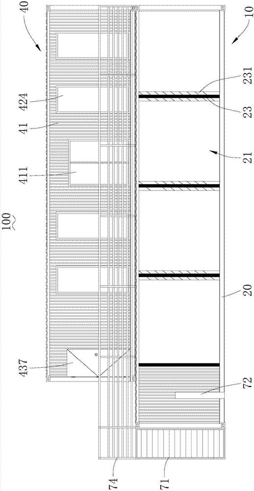
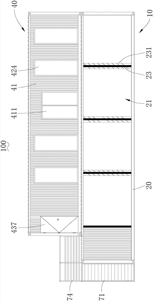
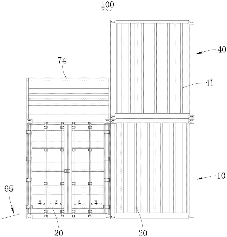
The invention provides a container charging service station. The container charging service station comprises a container charging station, a service container and stairs, wherein the service container and stairs are used for providing a rest site, the service container is installed at the top surface of the container charging station, the container charging station comprises a charging container which supports the service container, the charging container is internally provided with a central power distributor, a parking space for an electric vehicle to be parked is arranged below the service container, and a charging pile used for charging the electric vehicle is arranged at the lateral side of the parking space, and is electrically connected with the central power distributor. In the container charging service station, the charging container is utilized to form the container charging station, the service container is supported through the charging container, the arranged stairs can lead to the service container, so that the charging station for personnel to conduct guarding is conveniently spliced and assembled, assembly is conveniently conducted, the time is short, a waste container can be reused, and the cost is low; meanwhile, the parking space and the charging pile are arranged below the service container, and the electric vehicle can be protected while being charged.

Description

technical field [0001] The invention belongs to the field of electric vehicle charging stations, and more specifically relates to a container charging service station. Background technique [0002] Electric vehicles have rapidly entered people's daily life. With the increasing number of vehicles, it is urgent to solve the charging problem of electric vehicles. All places have entered the situation of building a large number of charging stations. At present, when electric vehicles are charged, it generally takes a long time, such as several hours, to be fully charged, so charging stations are generally equipped with personnel on duty. At present, manned charging stations need to build charging rooms and other facilities, and complete civil works are required, which makes the construction of charging stations often require long-term preparation plans and surveys, and the site engineering management is complicated during construction, requiring personnel and equipment. Many, ...

Claims


Application Information

Patent Timeline
Patent Type & Authority Applications(China)
IPC IPC(8): E04H6/00E04H6/42B60L11/18H02J7/00
CPCH02J7/0027E04H6/00E04H6/42B60L53/30B60L53/31Y02T10/7072Y02T10/70Y02T90/12
Inventor 牛涛刘平马超王琼
Owner 云杉智慧新能源技术有限公司
Learn More