
Spliced cabinet

A pair of cabinet technology, applied in the field of splicing cabinets, can solve the problems of poor waterproof and moisture-proof performance, high processing and production costs, and large overall weight of the cabinet, so as to improve the overall panel strength, reduce the overall weight, and achieve reasonable structural design. Effect

Pending Publication Date: 2022-04-05
谭海涛
View PDF0 Cites 0 Cited by
  • Summary
  • Abstract
  • Description
  • Claims
  • Application Information

AI Technical Summary

Problems solved by technology

[0003] Most of the existing cabinets are made of wood, with poor waterproof and moisture-proof performance, and are not suitable for use in kitchens, bathrooms and other watery environments. If anti-rust metal cabinets are used, although the overall waterproof and moisture-proof performance is greatly improved, However, the overall weight of the cabinet is relatively large, and the processing and manufacturing costs are relatively high.

Method used


Image

  • Spliced cabinet
  • Spliced cabinet
  • Spliced cabinet

Examples


Embodiment 1

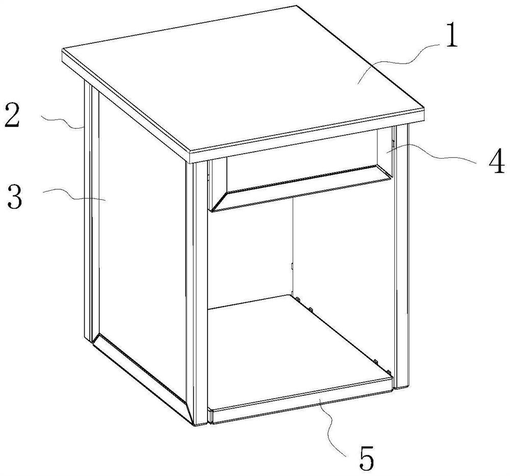
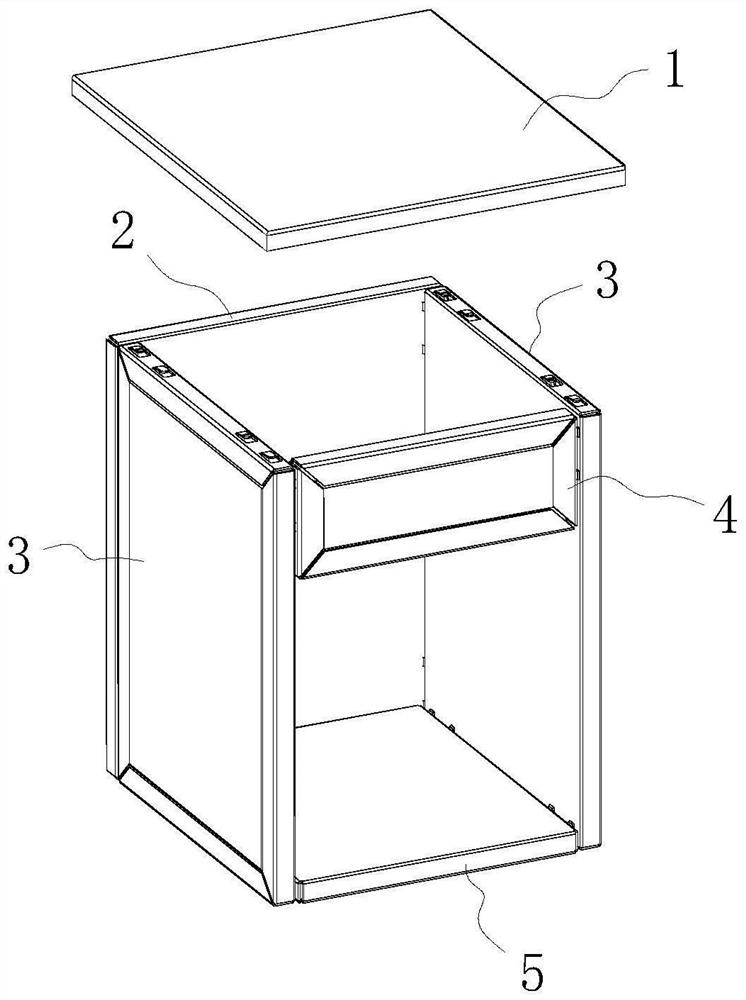
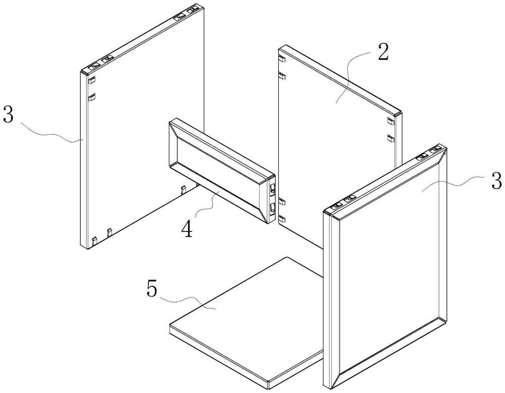
[0040] Example 1: See Figure 1-7 , a splicing cabinet, comprising a sheet metal back panel 2, a sheet metal side panel 3, a cabinet body sheet metal top panel 1, a sheet metal bottom panel 5, and a sheet metal crossbeam 4, the left and right sides of the end face inner wall of the sheet metal back panel 2 Distributed with at least one pair of buckle parts 9;

[0041] The end inner wall in this embodiment refers to the end wall corresponding to the sheet metal back panel 2 , the sheet metal side panel 3 , the sheet metal bottom panel 5 , and the sheet metal beam 4 corresponding to the cabinet cavity.

[0042] The edge of the side wall of the sheet metal side plate 3 near the sheet metal back plate 2 is provided with at least one pair of inserting parts 8 for cooperating with the buckle part 9, and the lower end of the end face inner wall of the sheet metal side plate 3 is provided with at least one For the buckle parts 9, at least one pair of buckle parts 9 are distributed on...

Embodiment 2

[0055] Example 2: see Figure 8 , a splicing cabinet, the difference from Embodiment 1 is that it also includes a horizontal sheet metal partition 7 and a vertical sheet metal partition 6, and the side walls on the left and right sides of the horizontal sheet metal partition 7 are provided with sockets 8. The buckle part 9 corresponding to the insertion part 8 of the horizontal sheet metal partition 7 is arranged on the inner wall of the sheet metal side panel 3 and / or the end wall of the vertical sheet metal partition 6;

[0056] In this embodiment, the buckle part 9 corresponding to the insertion part 8 of the horizontal sheet metal partition 7 is arranged on the end face inner wall of the sheet metal side plate 3 and the end face wall of the vertical sheet metal partition 6 at the same time. The insertion part 8 on the left side of the sheet metal partition 7 is inserted into the buckle part 9 of the sheet metal side panel 3, and the insertion part 8 on the right side of th...

Embodiment 3

[0061] Example 3: See Figure 9-10 , a splicing cabinet, the difference from embodiment 2 is that the sheet metal back panel 2, the sheet metal side panel 3, the sheet metal bottom panel 5 and the sheet metal beam 4 all adopt the same sheet metal structure of the overall sheet metal, and the sheet metal The metal plate includes a sheet metal shell and a sheet metal outer cover shell. The sheet metal shell includes a sheet metal base plate 100 as the inner wall of the end face. The sides of the sheet metal base plate 100 are bent and extended to have side wall edges 101. The side wall of the edge 101 is bent and extended to have an end face edge 102, and the end face edge 102 is bent and extended to have an inner side wall edge 103 close to the sheet metal base plate 100;

[0062] The edge 103 of the inner side wall and the sheet metal base plate 100 form a sheet metal outer insert groove, and the sheet metal outer cover shell is embedded in the sheet metal outer insert groove,...


PUM


Abstract

The invention discloses a spliced cabinet, which comprises a metal plate back plate, metal plate side plates, a cabinet body metal plate top panel, a metal plate bottom plate and a metal plate cross beam, and is characterized in that at least one pair of buckling parts is distributed on the left side and the right side of the inner wall of the end surface of the metal plate back plate; the side wall edge, close to the metal plate back plate, of each metal plate side plate is provided with at least one pair of inserting parts used for being matched with the buckling parts, the lower end of the inner wall of the end face of each metal plate side plate is provided with at least one pair of buckling parts, and the upper end, away from the metal plate back plate, of the inner wall of the end face of each metal plate side plate is also provided with at least one pair of buckling parts. According to the invention, the structural design is reasonable, the sheet metal plates are clamped and connected through the insertion parts and the buckle parts, the positions of the buckle connection (joining) parts can be changed at will according to actual specific requirements, the splicing and assembling are convenient and rapid, and the whole cabinet cavity is divided into a plurality of branch cabinet cavities through the horizontal sheet metal partition plates and the vertical sheet metal partition plates. Therefore, splicing and assembling of the multi-door cabinet body are achieved, and various types of cabinet bodies such as a single-door cabinet body, a double-door cabinet body, a three-door cabinet body, a four-door cabinet body, a five-door cabinet body or a more-door cabinet body can be conveniently machined and manufactured.

Description

technical field [0001] The invention relates to the technical field of cabinets, in particular to a splicing cabinet. Background technique [0002] Cabinets are utensils for storing clothes, documents, books, etc., square or rectangular, generally made of wood or metal. The cabinet is a kind of rectangular furniture or office supplies, which is taller and larger, and can store items. [0003] Most of the existing cabinets are made of wood, with poor waterproof and moisture-proof performance, and are not suitable for use in kitchens, bathrooms and other watery environments. If anti-rust metal cabinets are used, although the overall waterproof and moisture-proof performance is greatly improved, However, the overall weight of the cabinet is relatively large, and the manufacturing cost is relatively high. [0004] How to design an energy-saving, environmentally friendly and recyclable cabinet that can be assembled and manufactured conveniently and quickly, and can save materia...

Claims


Application Information

Patent Timeline
IPC IPC(8): A47B81/00A47B87/00A47B47/00A47B96/20A47B97/00
Inventor 谭海涛
Owner 谭海涛
Learn More