Roll crusher

A roller crusher and roller technology, which is applied in the field of mining machinery, can solve the problems of inconvenient operation and inaccurate particle size control, and achieve the effects of convenient operation, precise particle size control and high control accuracy.

Inactive Publication Date: 2017-10-10
河池市一森机械有限责任公司
View PDF9 Cites 7 Cited by
  • Summary
  • Abstract
  • Description
  • Claims
  • Application Information

AI Technical Summary

Problems solved by technology

[0003] The technical problem to be solved by the present invention is to provide a roll crusher, which can solve the problems of inaccurate particle size control and inconvenient operation of existing roll crushers

Method used


Image

  • Roll crusher

Examples


Embodiment Construction

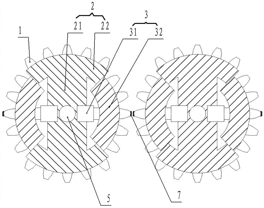
[0011] The present invention will be described in further detail below in conjunction with accompanying drawing embodiment:

[0012] figure 1 The shown roller crusher includes two rollers side by side, each roller has a sawtooth 1 on its outer wall, and each roller is driven to rotate by its own mandrel 5; each roller includes radial The fixed portion 2 and the radial extension portion 3; the radial fixed portion 2 includes a bearing mounting portion 21 and a first arc portion 22, the mandrel 5 is mounted on the core of the bearing mounting portion 21, and the first arc portion 22 has Two, respectively located at the two outer ends of the bearing mounting part 21; the radial extension part 3 includes two power cylinders 31 and two second arc parts 32, and the fixing parts of the two power cylinders 31 are respectively worn and fixed on On both sides of the bearing installation part 21 facing each other, the protruding ends of the two power cylinders 31 are respectively fixedl...


PUM


Abstract

The invention discloses a roller crusher, which belongs to the technical field of mining machinery. The roller crusher includes sawtoothed rollers whose outer walls are driven to rotate by their mandrels. The rollers are two side by side. Both of the two rollers include a radial fixing part and a radial extension part; the tip of the sawtooth located on the outer wall of the radial extension part is provided with a pressure sensor electrically connected to the controller. The invention can solve the problems of inaccurate particle size control and inconvenient operation of existing roller crushers.

Description

technical field [0001] The invention relates to the technical field of mining machinery, in particular to a roller crusher for crushing ore. Background technique [0002] Roller crusher is a kind of equipment for medium or fine crushing of limestone, slag, coke, coal and other materials; there is a roller crusher, including rollers, roller support bearings and roller driving devices, and the rollers are side by side The two rollers are equipped with sawtooth on the outer wall, a wedge-shaped device for adjusting the distance between the two rollers is installed between the two rollers, and the top of the wedge-shaped device is equipped with an adjusting bolt; when working , the material enters the crushing cavity of the machine, and is forced to pass between the two rollers under the action of the nip force when the roller shaft rotates. At the same time, the material is squeezed and sheared by the roller shaft and begins to break. The rotating tangent passes through the ga...

Claims


Application Information

Patent Timeline
IPC IPC(8): B02C4/08B02C4/30B02C4/32
CPCB02C4/08B02C4/30B02C4/32
Inventor 兰承宗周冠相
Owner 河池市一森机械有限责任公司
Why Eureka
Try Eureka