Staggered-tooth highlight milling cutter with chamfers and manufacturing method thereof

A manufacturing method and a technology of staggered teeth, applied to milling cutters, manufacturing tools, milling machine equipment, etc., can solve problems such as low processing efficiency, poor quality, and poor finish

Pending Publication Date: 2017-10-10
GUANGDONG DTECH TECH CO LTD
View PDF7 Cites 2 Cited by
  • Summary
  • Abstract
  • Description
  • Claims
  • Application Information

AI Technical Summary

Problems solved by technology

[0003] One of the objectives of the present invention is to provide a chamfered staggered-tooth high-gloss milling cutter for the deficiencies of the prior art. Low, poor finish, poor quality technical issues
The invention integrates the wrong-tooth cutter and the high-gloss cutter into one cutter, which solves the technical problems of low processing efficiency, poor finish and poor quality

Method used


Image

  • Staggered-tooth highlight milling cutter with chamfers and manufacturing method thereof
  • Staggered-tooth highlight milling cutter with chamfers and manufacturing method thereof

Examples


Embodiment 1

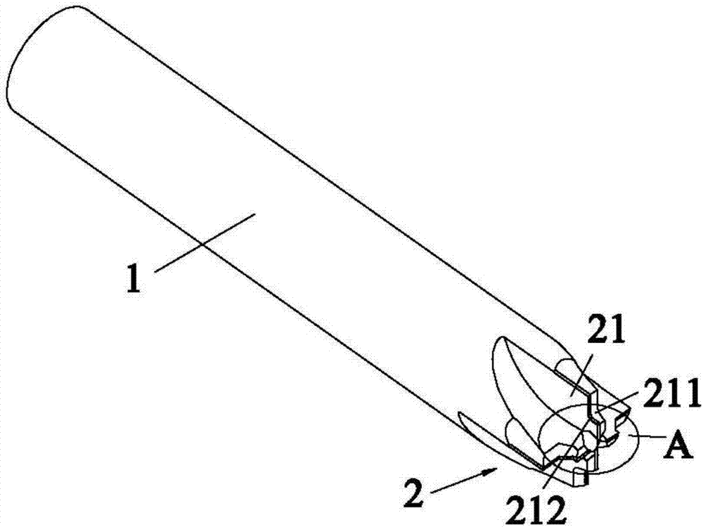
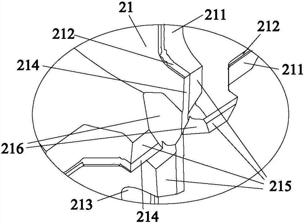
[0027] Such as Figure 1~2 As shown, a chamfered staggered-tooth high-gloss milling cutter includes a cutter bar 1 and a cutter head 2 integrally connected with the cutter bar 1. The cutter head 2 has several blades 21, and the number of blades 21 can be set as follows according to different requirements. Odd or even, each cutting edge 21 includes a step edge 211 and a wiper edge 212 connected to the step edge 211. The setting of the wiper edge 212 can enable the tool to meet the high finish requirements of the workpiece during use. The step edge 211 has Arc chamfering 213, arc chamfering 213 can be processed by the grinding wheel natural forming method and the contour trajectory method, the grinding wheel natural forming method: the contour is not programmed during edge cutting, and the required contour is obtained by interfering with the grinding wheel's own contour; Contour track method: the required contour can be achieved by program profiling during edge machining; the si...

Embodiment 2

[0032] A method for manufacturing a chamfered high-gloss milling cutter with staggered teeth in Embodiment 1, comprising the following steps:

[0033] Step 1. According to the processing requirements and effects of the above-mentioned staggered-tooth high-gloss milling cutter with chamfer, conduct design evaluation to determine whether the processing can be completed at one time, otherwise consider adopting the staggered-tooth structure;

[0034] Step 2. Complete the relevant drawing design and process documents;

[0035] Step 3. After receiving the material from the warehouse, use the manual step difference machine to carry out the step difference process of the above-mentioned high-gloss milling cutter with wrong teeth;

[0036] Step 4: After completing the step difference process, use a centerless grinder to control the outer diameter and process it to the required size;

[0037] Step 5. Use a laser laser machine to print a label on the outer diameter of the misaligned hig...


PUM


Abstract

The invention relates to the technical field of cutters, in particular to a staggered-tooth highlight milling cutter with chamfers. The milling cutter comprises a cutter rod and a cutter head connected with the cutter rod into a whole; the cutter head is provided with a plurality of blades; each blade comprises a stepped blade body and a dress-smooth blade body connected with the stepped blade body; and the stepped blade bodies are provided with the arc chamfers. According to the milling cutter, a staggered-tooth cutter and a highlight cutter are integrated onto one cutter, and the technical problems that the machining efficiency is low, the smooth finish is poor, and the quality is poor are solved. In addition, the invention further discloses a manufacturing method of the staggered-tooth highlight milling cutter with the chamfers.

Description

technical field [0001] The invention relates to the technical field of cutters, in particular to a chamfered chamfered high-gloss milling cutter and a manufacturing method thereof. Background technique [0002] Staggered-tooth high-gloss milling cutters are generally made of cemented carbide, which has the characteristics of high speed, high precision, and high efficiency. At present, the wrong-tooth high-gloss milling cutter is formed by a combination of multiple tools, which is easy to cause cumulative errors and poor finish. In addition, the existing staggered-tooth cutters and high-gloss cutters are difficult to process, and they are produced separately in conventional production, which makes the processing efficiency at the end of use low and the quality is not good. Contents of the invention [0003] One of the objectives of the present invention is to provide a chamfered staggered-tooth high-gloss milling cutter for the deficiencies of the prior art. Low, poor fini...

Claims


Application Information

Patent Timeline
Patent Type & Authority Applications(China)
IPC IPC(8): B23C5/00B23P15/34
CPCB23C5/00B23P15/34
Inventor 陈汉泉杨肖余伟
Owner GUANGDONG DTECH TECH CO LTD
Why Eureka
Try Eureka