Material conveying device for concrete mixing plant

A mixing station and concrete technology, which is applied in the field of conveying devices for concrete mixing stations, can solve the problems of uncontrollable lifting angle of conveying materials and inability to adjust the height of conveying pipes, etc., so as to improve the scope of use and practicability, facilitate cleaning and maintenance, The effect of easy cleaning

Inactive Publication Date: 2017-10-10
黔西南州启腾矿山设备有限公司
View PDF6 Cites 5 Cited by
  • Summary
  • Abstract
  • Description
  • Claims
  • Application Information

AI Technical Summary

Problems solved by technology

[0003] However, the existing conveying devices for concrete mixing plants have some shortcomings during use. The height of the conveying pipe cannot be adjusted, and the lifting angle of the conveying material cannot be controlled. Secondly, the conveying pipe as a whole is a sealed structure, and the conveying pipe Tube cleaning and maintenance are very convenient

Method used


Image

  • Material conveying device for concrete mixing plant
  • Material conveying device for concrete mixing plant
  • Material conveying device for concrete mixing plant

Examples


Embodiment 1

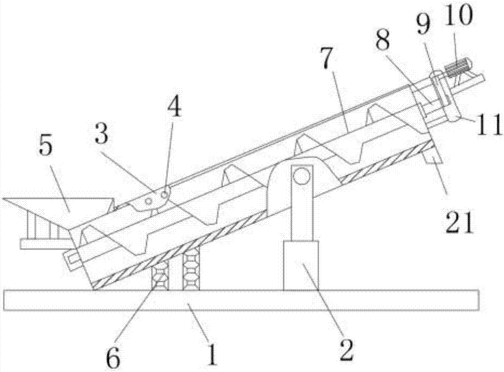
[0024] Embodiment one, with reference to Figure 1-3 , a conveying device for a concrete mixing station, comprising a base plate 1 and a feed pipe 3, a hydraulic telescopic rod 2 is connected at the middle position between the base plate 1 and the feed pipe 3, and the hydraulic telescopic rod 2 and the base plate 1 are perpendicular to each other, and the base plate 1 and the feeding pipe 3 are located on one side of the hydraulic telescopic rod 2 and are connected with an elastic rod 6. The top shell at one end of the feeding pipe 1 is welded with a feeding port 5, and the bottom shell at the other end of the feeding pipe 1 is provided with a Outlet 21, an overflow hole 4 is provided on the surface shell of the feeding pipe 1, a screw feeding shaft 7 is arranged at the inner center of the feeding pipe 1, and a connecting shaft 8 is fixed at one end of the screw feeding shaft 7, and The connecting shaft 8 is connected with the transmission motor 10 through the belt 9, the belt...

Embodiment 2

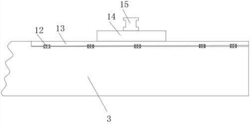
[0025] Embodiment two, refer to figure 1 with figure 2 The feeding pipe 3 is a rectangular structure, and the opening at the top of the feeding pipe 3 is connected with a sealing cover 13 by a hinge 12, and a gasket is provided at the junction of the sealing cover 13 and the feeding pipe 3, and the sealing cover 13 is arranged so that the feeding The feed pipe 3 is not a fully enclosed structure, which is convenient for cleaning and maintenance of the internal structure of the feed pipe 3, and also facilitates the dredging when the feed pipe 3 is blocked during improper operation.

Embodiment 3

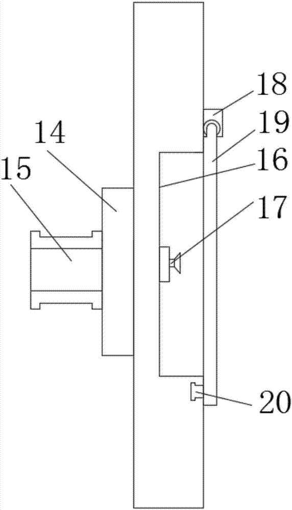
[0026] Embodiment three, refer to Figure 1-3 , a booster pump 14 is provided at the center of the top shell of the seal cover 13, and a water inlet pipe 15 is connected to the booster pump 14, a groove 16 is opened at the center of the back of the seal cover 13, and the inner bottom plate of the groove 16, etc. A spray head 17 is arranged at the distance, and a seal plate 19 is provided at the opening of the groove 16, and one end of the seal plate 19 is rotatably connected with the seal cover 13 through a rotating shaft 18, and the other end of the seal plate 19 is provided with an elastic buckle 20. The setting can realize the self-cleaning of the feeding pipe 3, which makes the feeding device more convenient to use. The setting of the booster pump 14 increases the water pressure, improves the pressure of the water sprayed by the nozzle 17, improves the quality of its flushing, and seals The arrangement of the plate 19 can seal the groove 16. When the nozzle 17 is not used,...


PUM


Abstract

The invention discloses a material conveying device for a concrete mixing plant. The material conveying device comprises a bottom plate and a material conveying pipe. A hydraulic telescopic rod is connected with the position between the bottom plate and the material conveying pipe, the hydraulic telescopic rod is perpendicular to the bottom plate, and an elastic rod is connected with the position, on one side of the hydraulic telescopic rod, between the bottom plate and the material conveying pipe; and a charging port is welded in a shell body of the top of one end of the material conveying pipe, a discharging port is formed in a shell body of the bottom of the other end of the material conveying pipe, an overflowing hole is formed in a shell body of the surface of the material conveying pipe, and a spiral material conveying shaft is arranged at the center of the inner portion of the material conveying pipe. According to the material conveying device for the concrete mixing plant, firstly the middle position of the material conveying pipe is fixedly connected with the bottom plate through the hydraulic telescopic rod, one end of the material conveying pipe is fixedly connected with the bottom plate through the elastic rod, the hoisting height of material conveying can be controlled through adjustment of the height of the hydraulic telescopic rod in the using process, material conveying to storing devices with different heights is facilitated, and the application range and the practicability of the material conveying device are promoted.

Description

technical field [0001] The invention relates to the technical field of concrete mixing plants, in particular to a material delivery device for a concrete mixing plant. Background technique [0002] Concrete mixing plant is a building material manufacturing equipment composed of five major components: mixing host, material weighing system, material conveying system, material storage system, control system and other auxiliary facilities. The main principle of its work is to use cement as the cementing material. Sandstone, lime, cinder and other raw materials are mixed and stirred, and finally made into concrete, which is put into construction and production as wall materials. Since the concrete mixing plant was put into use, it has been playing an important role in my country's building materials industry. Of course, this is also determined by the superior characteristics of the concrete mixing plant itself. The concrete mixing plant is mainly divided into sand and gravel feed...

Claims


Application Information

Patent Timeline
Patent Type & Authority Applications(China)
IPC IPC(8): B28C9/02
CPCB28C9/02
Inventor 张超
Owner 黔西南州启腾矿山设备有限公司
Why Eureka
Try Eureka