Plate conveying device with speed regulating function

A speed regulating device, plate technology, applied in the direction of conveyor, transportation and packaging, to achieve the effect of simple and efficient structure, flexible and convenient use

Inactive Publication Date: 2017-10-10
ANHUI TECHN COLLEGE OF MECHANICAL & ELECTRICAL ENG
View PDF7 Cites 3 Cited by
  • Summary
  • Abstract
  • Description
  • Claims
  • Application Information

AI Technical Summary

Problems solved by technology

Although above-mentioned prior art is reasonable in structure, reduces cost, can't solve the above-mentioned problem

Method used


Image

  • Plate conveying device with speed regulating function
  • Plate conveying device with speed regulating function

Examples


Embodiment Construction

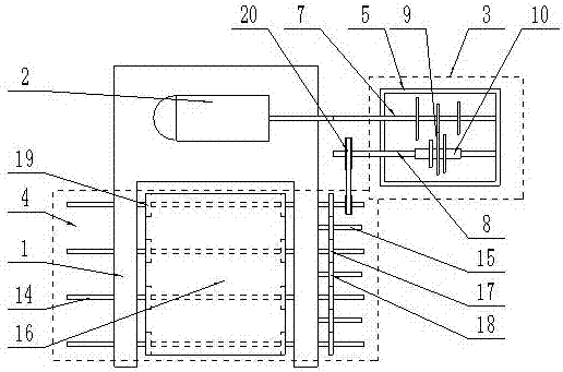
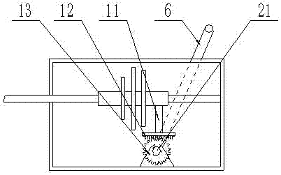
[0015] The present invention is specifically described below in conjunction with accompanying drawing, as Figure 1-2 As shown, a plate conveying speed regulating device includes a bracket, a motor, a speed regulating mechanism and a transmission mechanism. The speed regulating mechanism is composed of a speed regulating box, a speed regulating lever, a first transmission shaft, a second transmission shaft and multiple sets The first transmission shaft and the second transmission shaft are installed inside the speed control box, the second transmission shaft is provided with a sleeve, and the multiple sets of gears are respectively installed on the first transmission shaft and the sleeve, The bushing is connected to the slider, and the lower surface of the slider is provided with a rack structure, and the slider is connected to a pinion through the rack structure, and the pinion is connected to the speed regulating rod; the transmission mechanism is composed of a plurality of m...


PUM


Abstract

The invention discloses a plate conveying device with a speed regulating function. The plate conveying device comprises a bracket, a motor, a speed regulating mechanism and a transmission mechanism, wherein the speed regulating mechanism comprises a speed regulating box, a speed regulating rod, a first transmission shaft, a second transmission shaft and a plurality of groups of gears; the first transmission shaft and the second transmission shaft are mounted in the speed regulating box; a shaft sleeve is arranged on the second transmission shaft; the plurality of groups of gears are mounted on each of the first transmission shaft and the shaft sleeve; the shaft sleeve is connected with a sliding block; a toothed rack structure is arranged on the lower surface of the sliding block; the sliding block is connected with a pinion through the toothed rack structure; and the pinion is connected with the speed regulating rod. The plate conveying device has the benefits as follows: the conveying speed can be regulated, the use is flexible and convenient, and the structure is simple and efficient.

Description

technical field [0001] The invention relates to the field of plate production, in particular to a plate conveying speed regulating device. Background technique [0002] Panels are usually manufactured as flat rectangular building material panels of standard sizes for use as wall, ceiling or floor elements. It also refers to forged, rolled or cast metal plates. Divided into thin plate, medium plate, thick plate, extra thick plate, usually made into flat rectangular building material plates of standard size. [0003] The invention with the application number of 201020582750.1 is a plate conveying frame which has the same technical field as the present invention. The invention named a plate conveying frame includes a support, and at least two parallel rows of conveying wheels are arranged on the support in the advancing direction of conveying materials, and each row of conveying wheels includes a plurality of parallel conveying wheels. The invention has reasonable structure ...

Claims


Application Information

Patent Timeline
Patent Type & Authority Applications(China)
IPC IPC(8): B65G23/24B65G23/30B65G15/00
CPCB65G23/24B65G15/00B65G23/30
Inventor 刘彦春
Owner ANHUI TECHN COLLEGE OF MECHANICAL & ELECTRICAL ENG
Why Eureka
Try Eureka