
Vehicle, engine and crankshaft balance structure of engine

A balanced structure and engine technology, applied in the field of vehicles, can solve the problems of high cost of process changes, increased unbalance of single and double-mass flywheels, and lack of universality

Inactive Publication Date: 2017-10-10
BEIQI FOTON MOTOR CO LTD
View PDF4 Cites 11 Cited by
  • Summary
  • Abstract
  • Description
  • Claims
  • Application Information

AI Technical Summary

Problems solved by technology

However, first of all, relying solely on several balance blocks of the crankshaft itself can only balance part of the moment of inertia. For example, in a three-cylinder engine, only 52% of the moment of inertia can be balanced, and its balance performance is still insufficient; There are three types of flywheels and dual-mass flywheels. The amount of unbalance that can be designed on the flexible disc is extremely limited. The increase of unbalance in single- and dual-mass flywheels is also restricted by related engine accessories. The cost of process modification is huge. This method can only be applied to a few models. engine, not universal

Method used


Image

  • Vehicle, engine and crankshaft balance structure of engine
  • Vehicle, engine and crankshaft balance structure of engine
  • Vehicle, engine and crankshaft balance structure of engine

Examples


Embodiment Construction

[0027] The following will clearly and completely describe the technical solutions in the embodiments of the present invention with reference to the accompanying drawings in the embodiments of the present invention. Obviously, the described embodiments are only some, not all, embodiments of the present invention. Based on the embodiments of the present invention, all other embodiments obtained by persons of ordinary skill in the art without making creative efforts belong to the protection scope of the present invention.

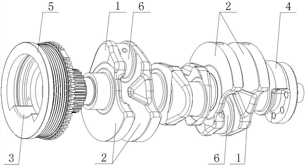
[0028] Please refer to figure 1 , figure 1 It is a schematic diagram of the overall structure of a specific embodiment provided by the present invention.

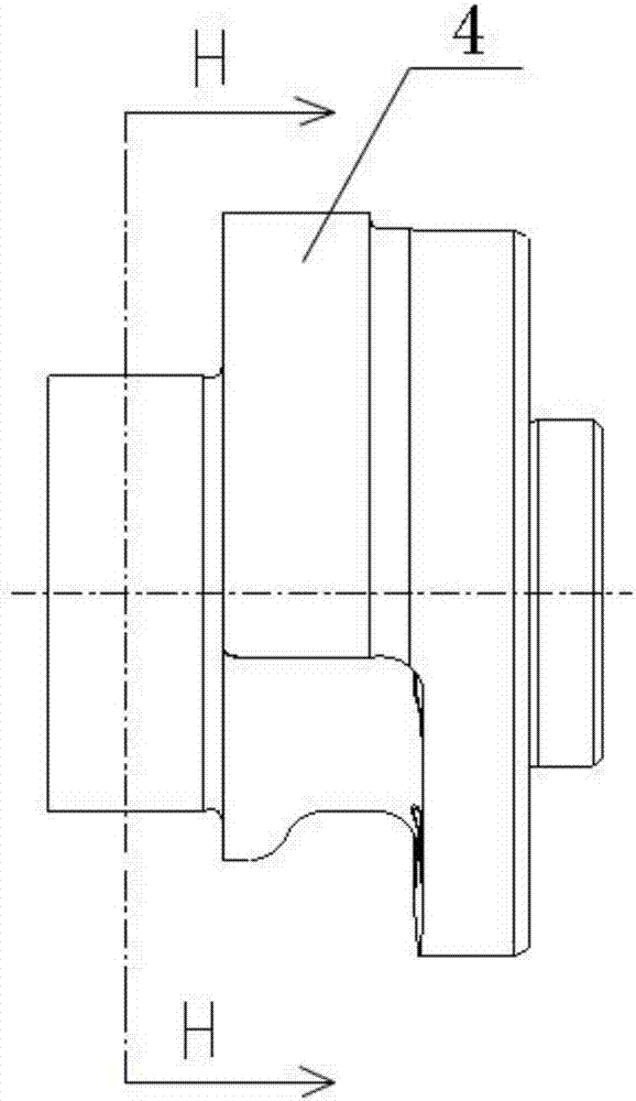
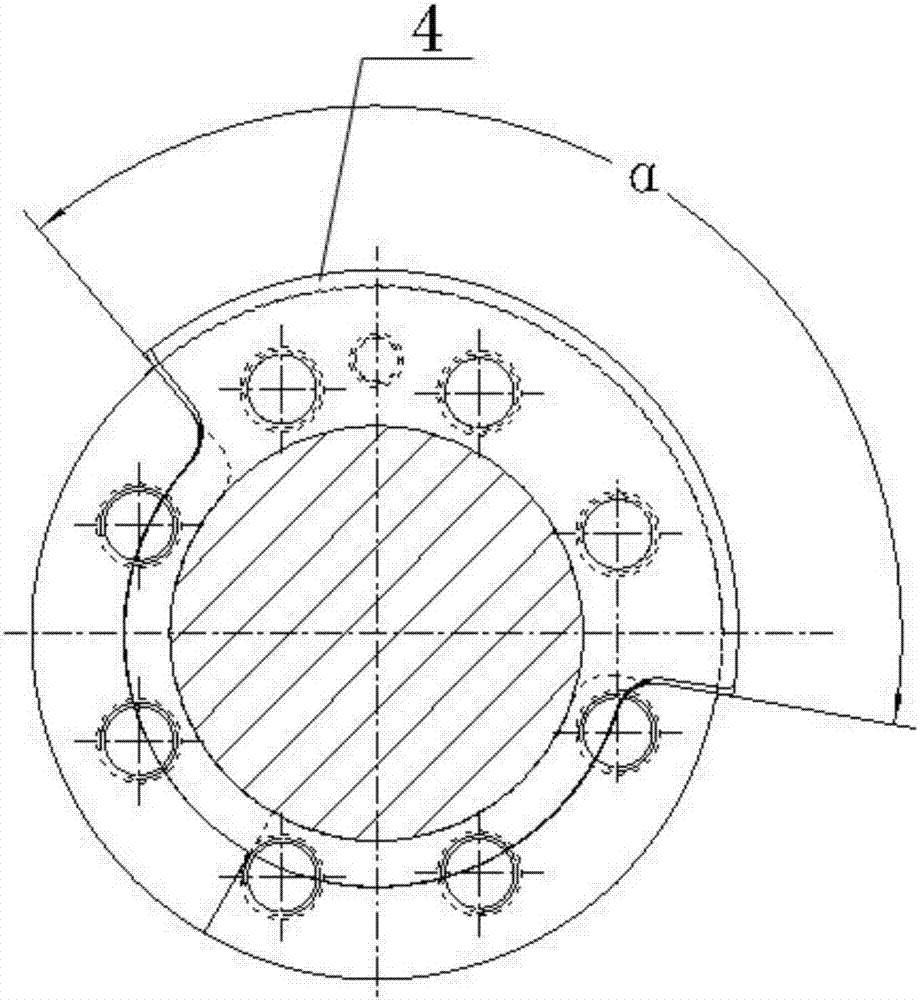
[0029] In a specific embodiment provided by the present invention, the crankshaft balance structure of the engine mainly includes a balance weight 2 , a first counterweight 3 and a second counterweight 4 .

[0030] Among them, the balance weight 2 is arranged on several groups of crank arms 1 on the crank...


PUM


Abstract

The invention discloses a crankshaft balance structure, which includes balance weights respectively arranged on several groups of crank arms with equal weight, and also includes a first counterweight arranged at the front end of the crankshaft and a second counterweight arranged at the rear end of the crankshaft. The mass of the first balance weight and the second balance weight are equal, the direction of the center of mass is opposite, and the direction of the center of mass of one of them is the same as the direction of the center of mass of the balance weight on the adjacent crank arm. In this way, the balance of the inertial force is maintained through the characteristics of the first counterweight and the second counterweight being equal in weight and reversed, and at the same time, one of them is in the same direction as the center of mass of the counterweight on the adjacent crank arm, so that the rotational inertia moment can be achieved Full balance and semi-balance of reciprocating inertia moment meet the basic balance design goal of the crankshaft system. Compared with the existing technology, there is no need to change the structure of the front and rear parts of the engine (such as the flywheel), which improves the universality and versatility . The invention also discloses an engine and a vehicle, the beneficial effects of which are as described above.

Description

technical field [0001] The invention relates to the technical field of vehicle engineering, in particular to a crankshaft balance structure of an engine. The present invention also relates to an engine including the above crankshaft balance structure and a vehicle. Background technique [0002] With the development of China's machinery industry, more and more machinery and equipment have been widely used. [0003] There are a large number of parts on the vehicle, up to tens of thousands, including several systems, mechanisms, assemblies, etc., such as the five major systems and two major mechanisms of the engine, as well as the driving system, steering system, braking system and various electronic modules. , sensors, etc. [0004] The engine is the most important part of the vehicle and is the driving force for the movement of the vehicle. There are many parts on the engine, such as crankshaft flywheel set, piston connecting rod set and cylinder block, throttle valve, fue...

Claims


Application Information

Patent Timeline
Patent Type & Authority Applications(China)
IPC IPC(8): F16F15/14F16F15/26F16C3/20
CPCF16F15/1464F16C3/20F16F15/26
Inventor 吴天亭
Owner BEIQI FOTON MOTOR CO LTD
Learn More