
A Method of Regional Centralized Energy Supply

An energy supply and regional technology, applied in the direction of machine operation, refrigerator, heating and cooling combination, etc., can solve the problems of poor system economy and high initial investment, reduce investment, reduce pump consumption and heat loss, The effect of reducing the pipe diameter

Active Publication Date: 2020-03-31
江苏氿川能源科技有限公司
View PDF5 Cites 0 Cited by
  • Summary
  • Abstract
  • Description
  • Claims
  • Application Information

AI Technical Summary

Problems solved by technology

[0007] The present invention aims at the problem of high initial investment and poor system economy in the prior art of adopting a main station for centralized energy supply in the region, and researches and designs a regional centralized energy supply method with small initial investment and good system economy

Method used


Image

  • A Method of Regional Centralized Energy Supply
  • A Method of Regional Centralized Energy Supply
  • A Method of Regional Centralized Energy Supply

Examples


Embodiment 1

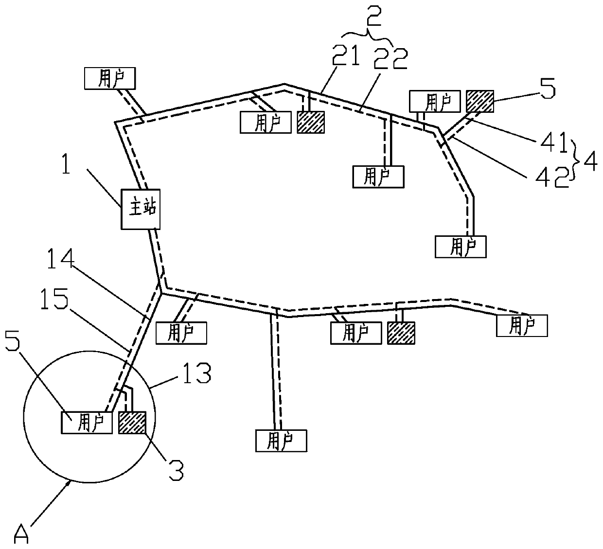
[0032] Such as Figure 2-Figure 4 As shown, when there are few users 5 in the area, it can generally be set that when the number of users 5 in the area is less than or equal to 50% of the households in the entire area, the user-side energy supply equipment 3 is used to meet the load demand of users 5. When the number of users 5 gradually increases When the user 5 in the area is greater than 50% of the households in the entire area, the master station 1 with higher energy efficiency will be put into use. The master station 1 can adopt technologies with high energy efficiency such as renewable energy and / or combined cooling, heating, and power systems. The energy supply equipment on the user side adopts air-cooled heat pumps, gas boilers and other equipment with relatively low energy efficiency, small investment and simple structure.

[0033] The regional centralized energy supply method of the present invention comprises the following steps:

[0034] S1. When there are few us...

Embodiment 2

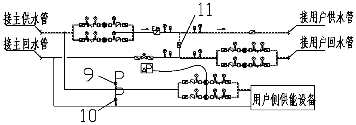
[0045] Such as Figure 5 As shown, the difference compared with Embodiment 1 is that the user 5 is indirectly connected to the main energy supply station 1 , and a plate heat exchanger 12 is arranged between the user 5 and the main energy supply station 1 .


PUM


Abstract

The invention relates to the technical field of region heat supply / cold supply systems, and particularly discloses a region concentrated energy supply system. The region concentrated energy supply system comprises one main station, at least one main energy supply pipe, a plurality of user side energy supply devices and an auxiliary energy supply pipe, and the energy efficiency of the main station is larger than the energy efficiency of the user side energy supply devices; one end of the main energy supply pipe is connected with the main station, and the other end of the main energy supply pipe is connected to users at the far ends; and the user side energy supply devices are connected with at least one nearby user in a nearby manner, one end of the auxiliary energy supply pipe is connected with the user side energy supply devices, and the other end of the auxiliary energy supply pipe is connected to the main energy supply pipe. A region concentrated energy supply method is further disclosed. The region concentrated energy supply method includes the following steps that S1, when the users in a region are fewer, the user side energy supply devices are built at the positions close to the users; and S2, along with increase of the users in the region, the main station is built. By means of the region concentrated energy supply system and method, investment is greatly reduced; and meanwhile, the system conveying pump consumption and heat losses are reduced, and the system economic efficiency is good.

Description

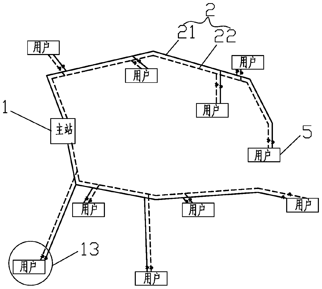
technical field [0001] The invention relates to the technical field of regional heating / cooling systems, in particular to a regional centralized energy supply method. Background technique [0002] With the large-scale promotion of central cooling and heating in the south, more and more places use renewable energy for regional centralized cooling and heating systems, such as figure 1 As shown, its main feature is to set up a renewable energy centralized cooling and heating station, set up multiple equipment units in the station, and supply energy to the outside through centralized pipelines. The main station 1 communicates with users 5 through water supply pipes and return water pipes. connected. [0003] This kind of system should mainly be used in areas with high volume ratios, using renewable energy or other high-energy-efficiency technologies, and setting up multiple energy sources in one energy station. The centralized supply of the pipeline network can improve the oper...

Claims


Application Information

Patent Timeline
Patent Type & Authority Patents(China)
IPC IPC(8): F25B29/00
CPCF25B29/00
Inventor 朱庭浩吴斯奇韦伟欧阳杰南王凭
Owner 江苏氿川能源科技有限公司
Learn More