Quick connector of magnetic type electrical test wire

A test line, magnetic suction technology, applied to the parts of electrical measuring instruments, measuring electrical variables, measuring device magnets, etc., can solve problems such as false touch, falling off, cumbersome connection operations, etc., to achieve convenient use and small contact resistance , The effect of speeding up the test process

Pending Publication Date: 2017-10-10
STATE GRID HEILONGJIANG ELECTRIC POWER COMPANY +1
View PDF12 Cites 7 Cited by
  • Summary
  • Abstract
  • Description
  • Claims
  • Application Information

AI Technical Summary

Problems solved by technology

[0007] The purpose of the present invention is to provide a quick connector for a magnetic suction type electrical test line in order t

Method used


Image

  • Quick connector of magnetic type electrical test wire
  • Quick connector of magnetic type electrical test wire
  • Quick connector of magnetic type electrical test wire

Examples


specific Embodiment approach 1

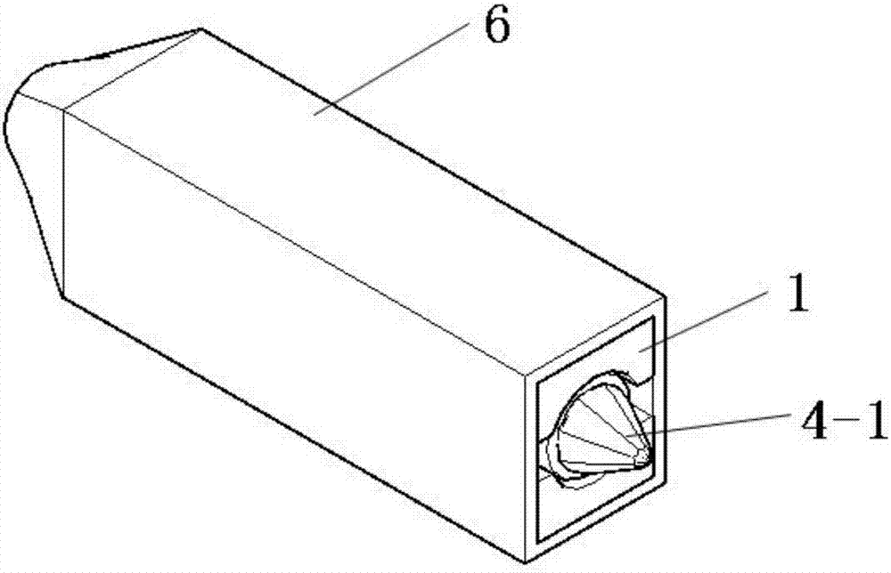
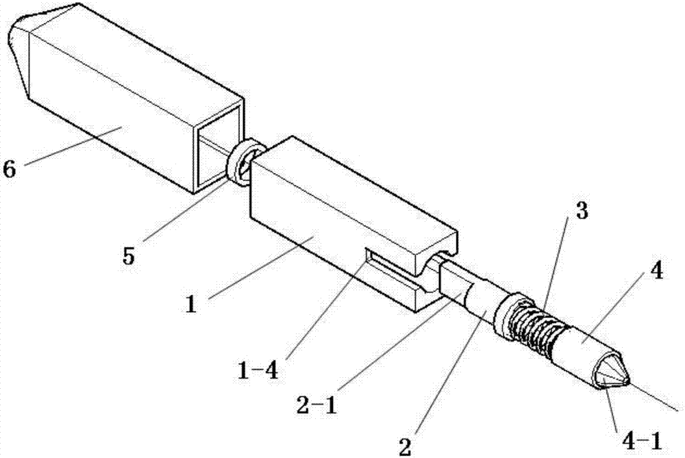
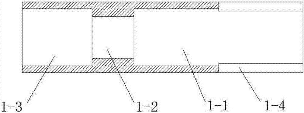
[0015] Specific embodiment 1: The quick connector of the magnetic suction type electrical test line in this embodiment includes an insulating sheath 6, an adsorption magnetic steel 1, a connecting bolt 2, a compression spring 3, a copper contact post 4 and a nut 5, and an adsorption magnetic steel 1 It is a rectangular block, and along the axial center line of the rectangular block, there are through holes consisting of contact hole 1-1, middle hole 1-2 and bolt hole 1-3. The contact hole 1-1 and the middle The hole 1-2 forms a stepped hole structure, one end of the compression spring 3 is set on the cap surface of the connecting bolt 2, the other end of the compression spring 3 is connected with the copper contact column 4, and the connecting bolt 2 is inserted into the middle hole 1-2 , the bolt rod of the connecting bolt 2 extends into the bolt hole 1-3, the nut 5 is tightly set on the bolt rod of the connecting bolt 2, the copper contact post 4 is located in the contact hol...

specific Embodiment approach 2

[0018] Embodiment 2: This embodiment differs from Embodiment 1 in that one end of the compression spring 3 is welded on the cap surface of the connecting bolt 2 , and the other end of the compression spring 3 is welded to the copper contact post 4 .

[0019] In this embodiment, the copper contact post, the compression spring, and the wire connection bolt are tightly welded into one body, so as to increase the electrical conductivity and reduce the measurement error caused by the wire.

specific Embodiment approach 3

[0020] Embodiment 3: The difference between this embodiment and Embodiment 1 or 2 is that there are opposite rectangular grooves 1-4 on the magnetic steel wall of the contact hole 1-1 section in the adsorption magnetic steel 1 .

[0021] The rectangular groove in this embodiment is along the axial direction of the cuboid body and communicates with the end face of the magnetic steel to facilitate the insertion and adsorption of some relay chip pins.


PUM

PropertyMeasurementUnit
Lengthaaaaaaaaaa

Abstract

The invention provides a quick connector of a magnetic type electrical test wire, relates to a magnetic type quick connector device and aims to solve the problem that an existing electrical test wire is complicated in connection operation and easily causes dropping and mistaken touch and the like. The quick connector of the magnetic type electrical test wire comprises an insulating sheath, attractive magnetic steel, a connecting bolt, a press spring, a copper contact column and a nut, wherein one end of the press spring is arranged on the surface of a bolt cap of the connecting bolt, the other end of the press spring is connected with the copper contact column, the connecting bolt is plugged into the attractive magnetic steel, a bolt rod of the connecting bolt is tightly sleeved with the nut, a copper contact is exposed out of the end face of the attractive magnetic steel, and the outer surface of the attractive magnetic steel is coated with the insulating sheath. A magnetic attraction function of the quick connector is utilized to complete fastening for guaranteeing connection, and good contact is guaranteed by utilizing pressing of the spring. Accordingly, the shortcomings existing in the test wiring process are overcome, and the working efficiency of an electric test is improved.

Description

technical field [0001] The invention relates to a magnetic suction type quick joint device. Background technique [0002] Generally, there are two main ways to connect the existing electrical test line: [0003] 1. Fix the test lead to the terminal block through the plug-in or pin-type connector for testing; [0004] This method is more secure in connection, but the terminal screw needs to be loosened and connected with the original wire in parallel. The operation is cumbersome and the reliability is low. When performing a small test, the workload will be increased, and the operation process is more cumbersome. It is easy to cause damage to the original wiring and terminals during a large number of frequent tests. [0005] 2. Use the crocodile clip quick connector to clamp on the terminal fastening screw for testing; [0006] This method is prone to risks such as falling off, touching other terminals by mistake and causing a short circuit. Contents of the invention [...

Claims


Application Information

Patent Timeline
IPC IPC(8): G01R1/04G01R1/16
CPCG01R1/0416G01R1/16
Inventor 刘吉强张瑞勇黄祖臻
Owner STATE GRID HEILONGJIANG ELECTRIC POWER COMPANY
Why Eureka
Try Eureka