
Pneumatic precision positioning mechanism with piezoelectric microdisplacement compensation function

A technology of precise positioning and displacement amplifying mechanism, which is applied to parts and instruments of instruments, etc., can solve the problems of poor positioning accuracy and application requirements of precision mechanical engineering, and achieve the effect of easy control, fast response speed, and compensation of output displacement error.

Active Publication Date: 2017-10-10
南京元稀世特自动化设备有限公司
View PDF6 Cites 3 Cited by
  • Summary
  • Abstract
  • Description
  • Claims
  • Application Information

AI Technical Summary

Problems solved by technology

[0005] In view of the poor positioning accuracy of the existing pneumatic positioning system that cannot meet the application requirements of precision mechanical engineering, this invention combines the advantages of piezoelectric ceramics and applies it to the pneumatic positioning system to propose a pneumatic precision positioning mechanism based on piezoelectric micro-displacement compensation. Pneumatic precision positioning mechanism for large stroke and high precision positioning

Method used


Image

  • Pneumatic precision positioning mechanism with piezoelectric microdisplacement compensation function
  • Pneumatic precision positioning mechanism with piezoelectric microdisplacement compensation function
  • Pneumatic precision positioning mechanism with piezoelectric microdisplacement compensation function

Examples


Embodiment Construction

[0016] The present invention will be described in further detail below in conjunction with the accompanying drawings, but the specific embodiments of the present invention are not limited thereto, and all that are based on the inventive spirit, features, modes and functions of the present invention are within the protection scope of the present invention.

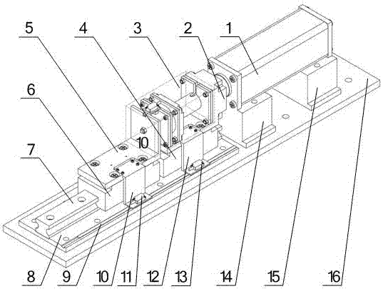
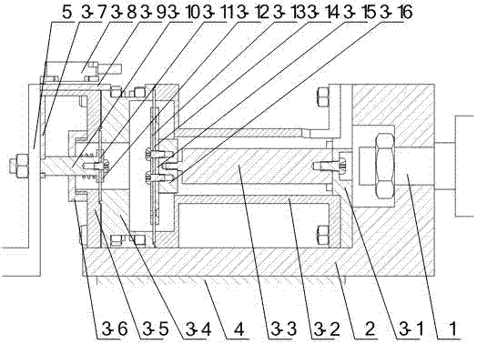
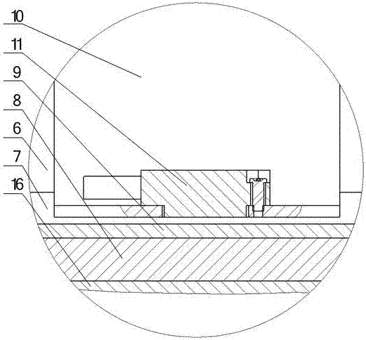
[0017] A pneumatic precision positioning mechanism for piezoelectric micro-displacement compensation of the present invention consists of a cylinder 1, a piezoelectric ceramic displacement amplification mechanism 3, a first slider 4, a second slider 6, a guide rail 7, a glass ruler 9 of a grating sensor, The second reading head 11 of the grating sensor, the first reading head 13 of the grating sensor, the worktable 16, the first connecting piece 14 and the second connecting piece 15 between the cylinder 1 and the working table 16, the cylinder 1 and the piezoelectric ceramic displacement amplification mechanism 3 and the fou...


PUM


Abstract

The invention provides a pneumatic precision positioning mechanism with a piezoelectric microdisplacement compensation function. The neumatic precision positioning mechanism consists of a cylinder, a piezo-ceramic displacement amplification mechanism, a second slider, a first slider, a guide rail 7, a glass ruler 9 of a grating sensor, a first reading head of a grating sensor, a second reading head of the grating sensor, a worktable, a first connecting piece, a second connecting piece, a sixth connecting piece, a fifth connecting piece, a seventh connecting piece and a third connecting piece, wherein the cylinder and the worktable are connected through the first connecting piece and the second connecting piece; the cylinder is connected with the piezo-ceramic displacement amplification mechanism and the first slider through the fourth connecting piece; the fourth connecting piece is connected with the first reading head of the grating sensor through the sixth connecting piece; a displacement output shaft of the piezo-ceramic displacement amplification mechanism is connected with the second slider through the fifth connecting piece; the fifth connecting piece is connected with the second reading head of the grating sensor through the seventh connecting piece; and the guide rail is connected with the worktable through the third connecting piece. According to the pneumatic precision positioning mechanism, microdisplacement output by piezo-ceramic is utilized to make up for output displacement accuracy of the cylinder, so that large-stroke high-precision positioning is realized.

Description

technical field [0001] The invention relates to a pneumatic precision positioning mechanism, in particular to a pneumatic precision positioning mechanism for piezoelectric micro-displacement compensation. Background technique [0002] Due to its low cost, energy saving, fast response, simple component structure, high work efficiency, convenient use and maintenance, high power-to-weight ratio, strong anti-interference, convenient centralized air supply and no pollution, etc., the pneumatic system is widely used in machinery. , transportation, chemical industry, metallurgy, mining, microelectronics, bioengineering, food, textile, medicine and military and other industrial sectors have been widely used. The traditional pneumatic system adopts mechanical positioning and throttle valve speed regulation, which often cannot meet the automatic control requirements of many equipment. However, the electric-pneumatic proportional or servo control system can realize multi-point steples...

Claims


Application Information

Patent Timeline
Patent Type & Authority Applications(China)
IPC IPC(8): G12B5/00
Inventor 许有熊朱松青周浩刘娣郝飞
Owner 南京元稀世特自动化设备有限公司
Learn More