Microstrip antenna array applied periodic spatial wave blocking and decoupling structure

A technology of microstrip antenna and space wave, which is applied in the direction of antenna array, antenna grounding switch structure connection, antenna coupling, etc., can solve the problem of affecting the antenna array bandwidth, radiation pattern and radiation efficiency, increasing the correlation of antenna units, and reducing the communication system Communication quality and other issues, to achieve the effect of miniaturized design, improved isolation, and compact structure

Active Publication Date: 2017-10-10
HARBIN ENG UNIV
View PDF3 Cites 16 Cited by
  • Summary
  • Abstract
  • Description
  • Claims
  • Application Information

AI Technical Summary

Problems solved by technology

However, in modern mobile communication equipment, the distance between each antenna unit is relatively small, which causes strong mutual coupling between the array units of the antenna array, which will not only affect the bandwidth, radiation pattern and radiation efficiency of the antenna array, etc. characteristics, it will also lead to an increase in the correlation between the antenna elements and reduce the communication quality of the communication system

Method used


Image

  • Microstrip antenna array applied periodic spatial wave blocking and decoupling structure
  • Microstrip antenna array applied periodic spatial wave blocking and decoupling structure
  • Microstrip antenna array applied periodic spatial wave blocking and decoupling structure

Examples


Embodiment 1

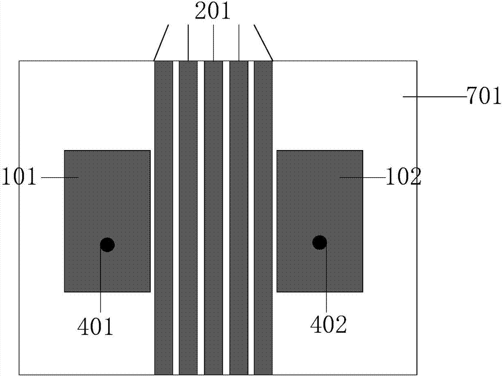
[0020] Such as figure 1 and figure 2 As shown, in order to reduce design costs and solve engineering problems, the dielectric substrate 701 used in the present invention is FR4 dielectric with a dielectric constant of 4.4, and the length and width of the dielectric substrate 701 are designed according to the principle of miniaturized microstrip antenna.

[0021] The common ground plate 301 of the antenna array under the dielectric substrate is a copper clad structure in actual engineering.

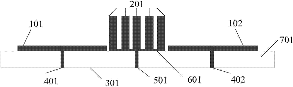
[0022] According to the electromagnetic wave theory and antenna array decoupling design theory, the three-dimensional periodic space wave blocking structure includes 5 space wave blocking units, each space wave blocking unit uses FR4 as the substrate, and each surface has a decoupling structure. The spatial wave blocking units are connected together through patches 601 , and finally connected to the common ground plate 301 through ground probes 501 . The distance between two adjacent sp...

Embodiment 2

[0024] Such as figure 2 As shown, a periodic space wave blocking decoupling structure for a microstrip antenna array of the present invention, the upper surface of the dielectric substrate 701 is printed with antenna rectangular radiation patches 101 and 102, and the antenna rectangular radiation patch is based on the rectangular microstrip Antenna theory is designed using copper printed material. The two coaxial feed ports 401 and 402 are respectively connected to SMA connectors, and the inner conductor of the SMA is connected to the antenna rectangular radiation patches 101 and 102 , and the outer conductor of the SMA is connected to the common ground plate 301 . The positions of the two coaxial feed ports 401 and 402 can be determined according to microstrip antenna design theory to meet the requirements of the working frequency of the antenna array.

Embodiment 3

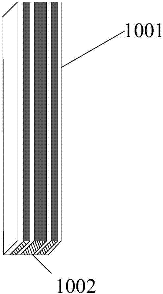
[0026] Such as image 3 As shown, each spatial wave blocking unit has a decoupling structure and presents a symmetrical distribution. The patch structure 1001 on its upper surface is three rectangular strip lines, the rectangular strip lines on both sides have the same size and are symmetrical about the center line, and the middle rectangular strip line is wider than the rectangular strip lines on both sides. The patch structure 1002 on the front and rear surfaces is also three rectangular strip lines. The rectangular strip lines on both sides have the same size and are symmetrical about the center line. same width and remain connected to each other. The left and right sides of each spatial wave blocking unit have the same decoupling structure, and the distances between adjacent spatial wave blocking units are equal. The distance between adjacent units and the size of each unit can be designed according to the engineering requirements and the decoupling frequency. The size o...


PUM


Abstract

The invention relates to a microstrip antenna array applied periodic spatial wave blocking and decoupling structure, which is used to reduce the coupling of array antennas and is realized through the loading of a periodic spatial wave blocking structure in the antenna array. The stereoscopic periodic spatial wave blocking structure is capable of reducing the coupling of the antenna array elements and increasing the separation of the antenna array. The structure comprises mainly a dielectric substrate 701, a commonly grounding plate 301, an antenna rectangular radiation patch 101 and an antenna rectangular radiation patch 102, a stereoscopic periodic spatial wave blocking structure 201, a patch 601, a grounding probe 501, and coaxially feed ports 401 and 402. The stereoscopic periodic spatial wave blocking structure designed by the invention cannot only effectively reduce the coupling in the antenna array, but also effectively increases the separation of the antenna array, and therefore, achieves the design of high-performance array antennas.

Description

technical field [0001] The invention belongs to the technical field of array antennas, and in particular relates to a periodic space wave blocking decoupling structure for a microstrip antenna array. Background technique [0002] In recent years, array antenna technology has been favored by scholars in the field of mobile communications, and has been widely used in base stations and radars. However, as people have higher and higher requirements for mobile communication devices, the array antenna technology is subject to many restrictions in the process of use, such as large volume and low gain. In addition, modern mobile communications require miniaturization and portability of equipment, which requires that the total space occupied by the array antenna units becomes small, so that the distance between the antenna array units becomes very small. The antenna array element spacing is one of the key parameters for array antenna design. When the distance is greater than one-hal...

Claims


Application Information

Patent Timeline
Patent Type & Authority Applications(China)
IPC IPC(8): H01Q1/38H01Q1/48H01Q1/50H01Q1/52H01Q21/00
CPCH01Q1/38H01Q1/48H01Q1/50H01Q1/523H01Q21/0006
Inventor 李迎松焦天奇姜弢
Owner HARBIN ENG UNIV
Why Eureka
Try Eureka