12/10 permanent magnet auxiliary excitation switched reluctance motor

A switched reluctance motor and auxiliary excitation technology, which is applied in the direction of magnetic circuits, electric components, electrical components, etc., can solve the problems of reducing magnetic flux closing reluctance, small torque, torque ripple and large noise, etc., to achieve increased Electromagnetic torque, effect of increasing saturation

Inactive Publication Date: 2017-10-10
BEIHANG UNIV +1
View PDF4 Cites 5 Cited by
  • Summary
  • Abstract
  • Description
  • Claims
  • Application Information

AI Technical Summary

Problems solved by technology

[0003] However, there are also many problems in the switched reluctance motor, which limit its further development, such as high motor loss, large torque ripple and noise during operation, difficult to obtain the motor model, and low utilization of the rotor surface, resulting in large volume torque. small wait
In the patent 201310263148.X, it is proposed to convert the 6-phase 12 / 10 structure switched reluctance motor into a 3-phase motor, that is, the magnetic pole teeth of two adjacent stator cores are shifted in opposite directions by 3° to obtain a motor with an unequal inner diameter of the stator , can shorten the magnetic flux closing path and reduce the reluctance during the magnetic flux closing process. Although the energy loss of the motor is reduced, the problem of increasing the output torque of the motor cannot be considered

Method used


Image

  • 12/10 permanent magnet auxiliary excitation switched reluctance motor
  • 12/10 permanent magnet auxiliary excitation switched reluctance motor
  • 12/10 permanent magnet auxiliary excitation switched reluctance motor

Examples


Embodiment Construction

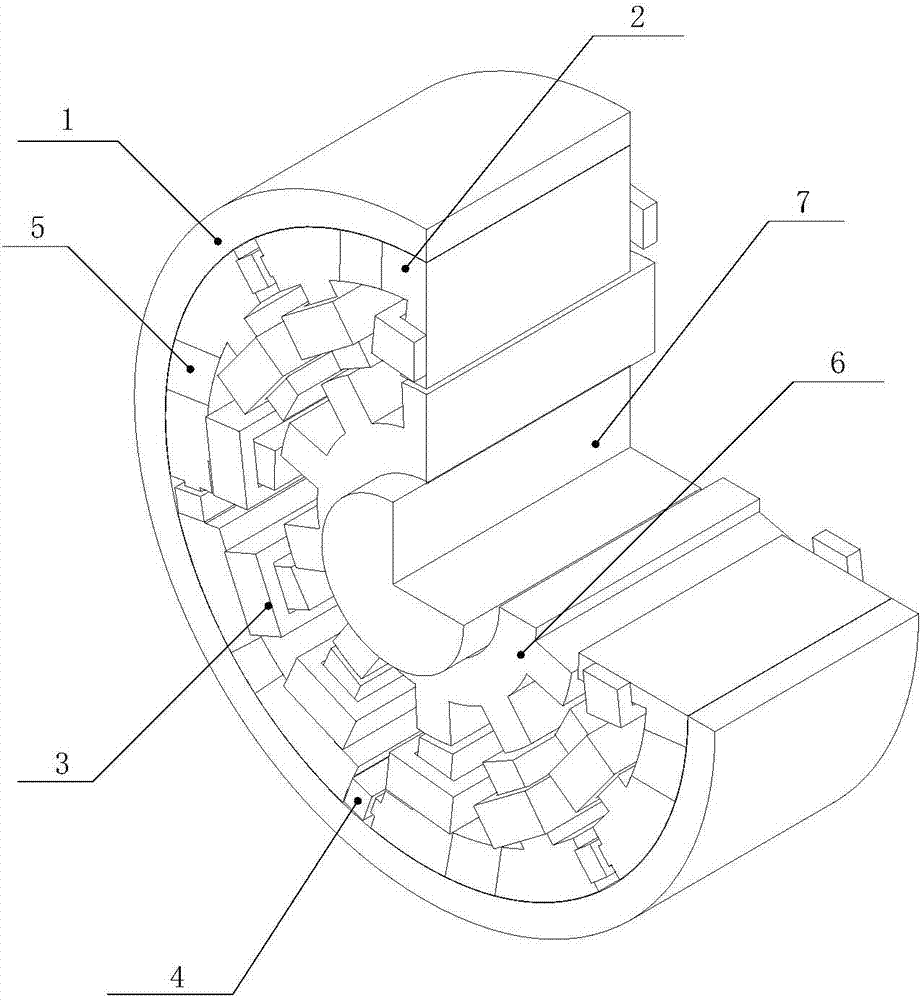
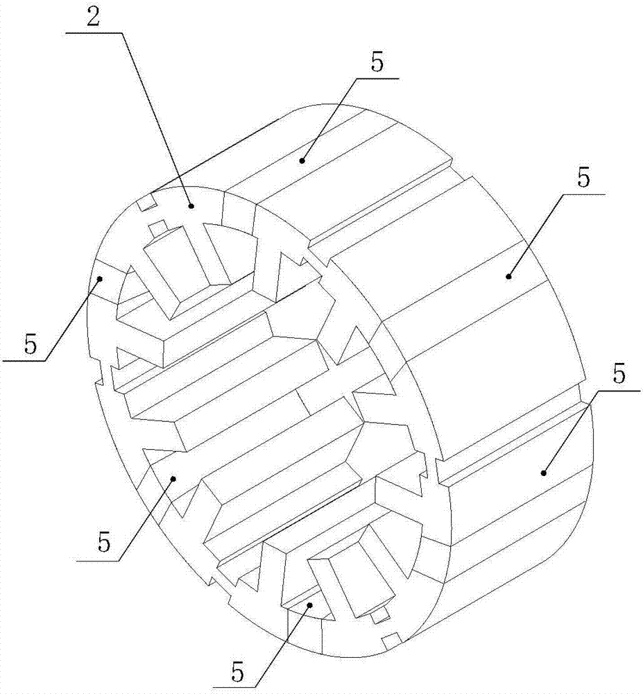
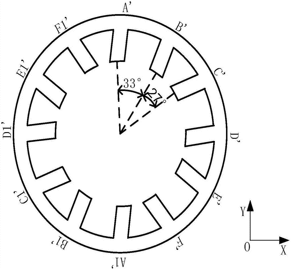
[0014] Such as figure 1 As shown, a 12 / 10 permanent magnet auxiliary excitation switched reluctance motor consists of a stator back yoke (1), a stator core (2), a torque winding coil (3), an auxiliary excitation coil (4), and a permanent magnet (5) , The rotor core (6) and the shaft (7) are composed. The inner side of the stator back yoke (1) is a stator core (2) and a permanent magnet (5), and the stator back yoke (1) is connected with the stator core (2) and the permanent magnet (5). The stator core (2) has 12 magnetic pole teeth, on which a torque winding coil (3) is wound, and the torque winding coil (3) provides a working magnetic field for the motor. The outer side of the stator core (2) is a stator back yoke (1), and the stator back yoke (1) is connected with the stator core (2). Define the outer diameter of the stator core (2) as r1, the inner diameter as r2, the stator tooth height as h1, and the stator tooth root arc length as λ. Among them, the inner diameter arcs...


PUM


Abstract

The invention proposes a 12 / 10 permanent magnet auxiliary excitation switched reluctance motor, composed of a stator back yoke, a stator iron core, a torque winding coil, an auxiliary excitation coil, a permanent magnet, a rotor iron core and a shaft. The stator iron core has 12 magnetic pole teeth, wound by the torque winding coil thereon; the outer side of the stator iron core is the stator back yoke, and the stator back yoke and the stator iron core are connected. The permanent magnet is embedded in the stator iron core's yoke part and the auxiliary excitation coil is wound in the auxiliary excitation winding mounting groove of the stator iron core's yoke. The inner part of the stator iron core is the rotor iron core, with a gap between the stator iron core and the rotor iron core to form an air gap. The rotor iron core has 10 magnetic pole teeth evenly distributed along its circumference, and the inner part of the rotor iron core is the shaft. The present invention provides excitation flux through a permanent magnet and an auxiliary field winding coil, thereby increasing the output torque of the motor.

Description

Technical field [0001] The invention designs a switched reluctance motor, in particular a permanent magnet auxiliary excitation switched reluctance motor, which can be used in wind power generation. Background technique [0002] In recent years, with the development of power electronics technology and the widespread application of microprocessors, the speed-regulating drive system based on switched reluctance motors has received extensive attention from scholars at home and abroad. The special stator and rotor structure of the switched reluctance motor makes it have the characteristics of simple and firm structure, high reliability and low manufacturing cost, which makes the switched reluctance motor widely used in the textile industry, aviation industry, mining industry, household appliances and electric vehicles. Applications. [0003] However, switched reluctance motors also have many problems, which limit their further development. For example, the motor has high loss, torque ...

Claims


Application Information

Patent Timeline
Patent Type & Authority Applications(China)
IPC IPC(8): H02K1/14H02K1/17H02K1/24H02K29/00
CPCH02K1/146H02K1/17H02K1/24H02K29/00H02K2201/03H02K2213/03
Inventor 王惠军庞明琪曲政魏新生张明举
Owner BEIHANG UNIV
Why Eureka
Try Eureka