Check patentability & draft patents in minutes with Patsnap Eureka AI!

data serialization circuit

A serialization, data technology, applied in parallel/serial conversion, electrical components, generation of electrical pulses, etc., can solve problems such as data quality degradation

Active Publication Date: 2020-12-04
NOVATEK MICROELECTRONICS CORP
View PDF6 Cites 0 Cited by
  • Summary
  • Abstract
  • Description
  • Claims
  • Application Information

AI Technical Summary

Problems solved by technology

The quality of the sampled data is reduced accordingly

Method used


Image

  • data serialization circuit
  • data serialization circuit
  • data serialization circuit

Examples


Embodiment Construction

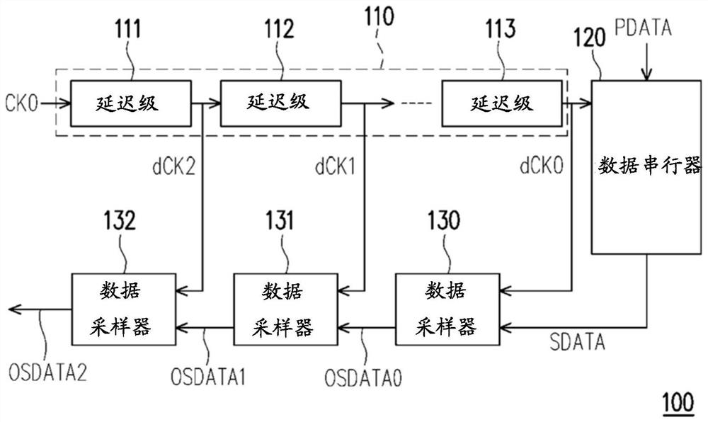
[0041] see figure 1 , figure 1 A schematic diagram illustrating a data serialization circuit 100 according to an embodiment of the present invention. The data serialization circuit 100 includes a delay circuit 110, a data serializer 120, and data samplers 130-132. The delay circuit 110 receives the input clock signal CK0 and generates a plurality of delayed clock signals dCK2-dCK0 by sequentially delaying the input clock signal CK0. Delay circuit 110 includes a plurality of delay stages, such as in figure 1 The three delay stages 111-113 are shown in . The delay stages 111-113 are coupled in series and generate delayed clock signals dCK2-dCK0 respectively. In this embodiment, the delayed clock signal dCK2 precedes the delayed clock signal dCK1, and the delayed clock signal dCK1 precedes the delayed clock signal dCK0. The delay stage 113 is the final delay stage, and the delayed clock signal dCK0 is the final stage delayed clock signal.

[0042] It can be seen that becaus...


PUM


Abstract

Data serialization circuit. The data serialization circuit includes a delay circuit, a data serializer, a first data sampler and a second data sampler. The delay circuit receives an input clock signal and generates a plurality of delayed clock signals. The delayed clock signal includes a first delayed clock signal generated by the first delay stage and a second delayed clock signal generated by the second delay stage. The data serializer receives parallel data and a final-stage delayed clock signal of the delayed clock signal, and converts the parallel data into serial data according to the final-stage delayed clock signal. Wherein, the first data sampler samples the serial data according to the first delayed clock signal to generate the first output serial data, and the second data sampler samples the first output serial data according to the second delayed clock signal to generate the first output serial data. Two output serial data.

Description

technical field [0001] The present invention relates to a data serialization circuit, and more particularly to a data serialization circuit with a lower jitter resampling scheme. Background technique [0002] In conventional technology, an integrated circuit (IC) requires multiple clock trees. A clock tree is used to provide multiple clock signals to the core circuitry of the IC. The core circuit may sample the data using the clock signal. In noisy power and / or ground environments, the jitter of each of the clock signals increases according to the number of delay stages of the clock tree used to generate each of the clock signals. Thus, the size of the window of the eye diagram corresponding to the data sampled by the clock signal with higher jitter is reduced. The quality of the sampled data is correspondingly reduced. SUMMARY OF THE INVENTION [0003] The present invention provides multiple data serialization circuits for achieving lower jitter of sampled data. [0...

Claims


Application Information

Patent Timeline
Patent Type & Authority Patents(China)
IPC IPC(8): H03M9/00
CPCH03M9/00H03K5/01H03K2005/00019H03K5/15046H03K3/037
Inventor 林士钧罗仁鸿陈慕蓉林永正
Owner NOVATEK MICROELECTRONICS CORP
Features
  • R&D
  • Intellectual Property
  • Life Sciences
  • Materials
  • Tech Scout
  • Unparalleled Data Quality
  • Higher Quality Content
  • 60% Fewer Hallucinations
Learn More