Solid electric heat storage equipment

An electric heat storage and solid technology, which is applied in heat storage equipment, lighting and heating equipment, fluid heaters, etc., can solve problems such as unsatisfactory use effect and complex structure, and achieve simple structure, high efficiency, and saving insulation materials Effect

Inactive Publication Date: 2017-10-13
辽宁赛科新能源技术开发有限公司
View PDF10 Cites 23 Cited by
  • Summary
  • Abstract
  • Description
  • Claims
  • Application Information

AI Technical Summary

Problems solved by technology

[0002] At present, most of the solid electric heat storage equipment on the market adopt the form of bottom return air, bottom heat exchange or bottom return air, upper heat exchange. The structure is complicated and the use effect is not ideal.

Method used


Image

  • Solid electric heat storage equipment
  • Solid electric heat storage equipment
  • Solid electric heat storage equipment

Examples


Embodiment 1

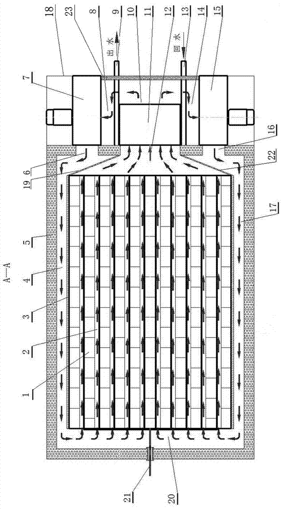
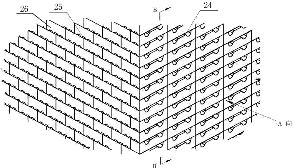
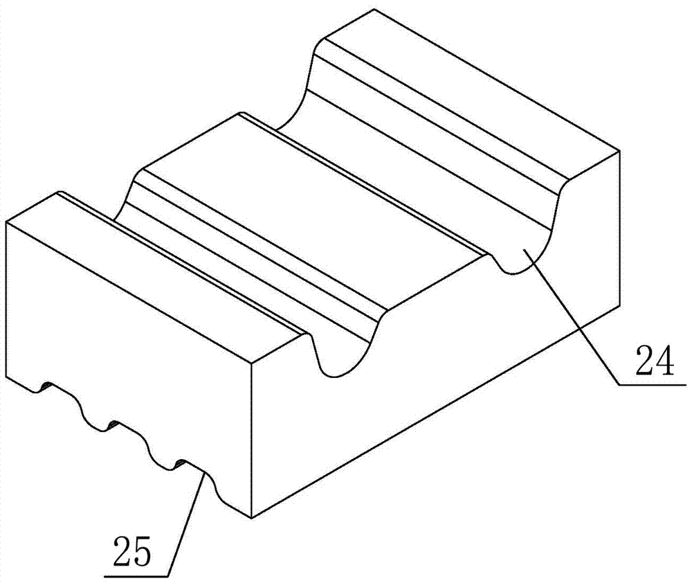
[0019] The solid electric heat storage device used in this embodiment includes a heat storage body 1, a fan 7, a fan 15, a heat exchanger 11 and a housing 18 with a power inlet 21, where the power inlet 21 can be used to connect Heating element. A shell insulation layer 5 is also provided on the inner wall of the shell 18, and a thermal storage body insulation layer 3 is also provided on the outside of the thermal storage body 1. The thermal storage body insulation layer 3 in this embodiment adopts a fire-blocking and thermal insulation board. A heat storage body ventilation duct 2 is provided between each heat storage brick layer in the body 1, and a return air duct is formed between the heat storage body heat preservation layer 3 and the shell heat preservation layer 5.

[0020] Between the inner wall of the shell insulation layer 5 located between the fan 7 and the heat exchanger 11 and the top end of the heat storage body insulation layer 3 is connected a fire prevention insu...


PUM


Abstract

The invention provides solid electric heat storage equipment and relates to the field of solid electric heat storage. The solid electric heat storage equipment is characterized in that a first air return duct communicates with an air return chamber, all air ventilation ducts in a heat storage body, and the inlet of a heat exchanger; a second air return duct is formed among a second fire-barrier insulation plate, a heat storage body insulation layer and a shell insulation layer; and through circulation air ducts on two sides, the circulation air of the solid electric heat storage equipment enters the heat storage body from the two sides after being blown from draught fans on the two sides. The solid electric heat storage equipment is simple in structure, lower in insulation material consumption, high in efficiency and the like, and can be popularized and utilized as a novel air circulation system for the solid electric heat storage equipment.

Description

Technical field [0001] The invention relates to the field of solid electric heat storage, in particular to a solid electric heat storage device. Background technique [0002] At present, most of the solid electric heat storage devices on the market adopt the form of bottom return air, bottom heat exchange or bottom return air, and upper heat exchange. The structure is relatively complex and the use effect is not ideal. Summary of the invention [0003] In view of the shortcomings of the prior art, the purpose of the present invention is to provide a solid electric heat storage device, which has the characteristics of good heat preservation effect, simple structure and high heat release efficiency. [0004] The technical scheme adopted by the present invention is: a solid electric heat storage device, including a heat storage body, a fan, a heat exchanger, and a shell with a power lead-in end, and a shell insulation layer is also provided on the inner wall of the shell to accumulate ...

Claims


Application Information

Patent Timeline
Patent Type & Authority Applications(China)
IPC IPC(8): F24H7/02F28D20/00
CPCF24H7/02F28D20/0056Y02E60/14
Inventor 文云峰张福源
Owner 辽宁赛科新能源技术开发有限公司
Why Eureka
Try Eureka