Method for detecting T-shaped groove in rotor rim of steam turbine

A steam turbine rotor and slot detection technology, which is used in measuring devices, material analysis using sonic/ultrasonic/infrasonic waves, and solids analysis using sonic/ultrasonic/infrasonic waves, etc. , low detection efficiency and other problems, to achieve the effect of improving detection efficiency, large scanning range, and realizing positioning and quantification

Inactive Publication Date: 2017-10-13
CENT CHINA BRANCH OF CHINA DATANG CORP SCI & TECH RES INST CO LTD
View PDF5 Cites 4 Cited by
  • Summary
  • Abstract
  • Description
  • Claims
  • Application Information

AI Technical Summary

Problems solved by technology

[0003] For the non-destructive testing of the T-groove of the steam turbine rotor flange, the current method is to use multiple probes with different angles to scan repeatedly, or to cover and scan the workpiece by moving a certain probe back and forth, which is very troublesome to scan. For example, the Chinese patent application publication number CN106053598A adopts this scanning method, and the signal emis

Method used


Image

  • Method for detecting T-shaped groove in rotor rim of steam turbine
  • Method for detecting T-shaped groove in rotor rim of steam turbine
  • Method for detecting T-shaped groove in rotor rim of steam turbine

Examples


Embodiment Construction

[0021] Embodiments of the present invention will be further described below in conjunction with the accompanying drawings.

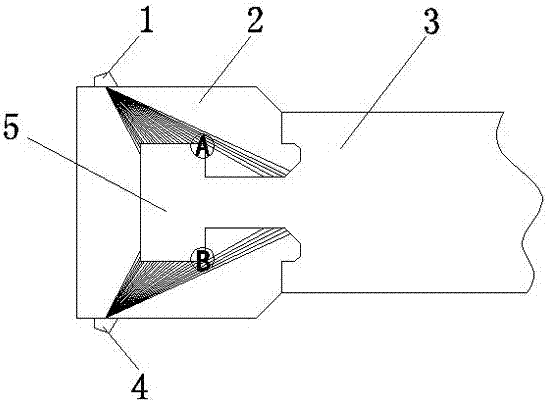
[0022] The specific embodiment of steam turbine rotor rim T-shaped groove detection method of the present invention is as follows: figure 1 As shown, when the steam turbine rotor is running at high speed, its blades are subjected to a large centrifugal force, and the centrifugal force is transferred to the T-shaped groove of the impeller flange through the T-shaped blade root, so that the T-shaped groove produces stress concentration in the sharp angle A and B areas , due to the harsh operating conditions of the steam turbine rotor, the stress concentration part is prone to stress corrosion cracks and fatigue cracks, so this part is the key detection area. Draw a two-dimensional model diagram of the T-groove of the impeller flange according to the structural size of the T-groove of the impeller flange to be inspected, and use the ultrasonic phased array ...


PUM


Abstract

The invention relates to a method for detecting a T-shaped groove in a rotor rim of a steam turbine. The method disclosed by the invention comprises the following steps: performing cover scanning on a to-be-detected position by adopting an ultrasonic phased array inspection device, performing time synchronization on interface waves and impulse transmission waves of the T-shaped groove, and compiling imaging software so as to realize ultrasonic phased array real-time imaging detection, so that the detection of the T-shaped groove in the rim is reliable and convenient, and misjudgment and missing detection can be avoided. Compared with the conventional ultrasonic detection method, the method disclosed by the invention has the advantages that the T-shaped groove of the impeller is subjected to flaw detection by adopting the ultrasonic phased array real-time imaging detection technology, full-coverage scanning of a reverse T-shaped groove can be completed under the conditions that the scanning range is wide, the defect waves are easily identified and a probe does not need to move back and forth, the detection efficiency is improved, and location and quantification of crack defects can be realized.

Description

technical field [0001] The invention relates to a method for detecting a T-shaped groove of a wheel flange of a steam turbine rotor. Background technique [0002] As the core component of a thermal power plant, the steam turbine rotor has long been affected by factors such as high temperature, high pressure, centrifugal force, exciting force, corrosion, vibration, and water droplet erosion in the wet steam area. The working conditions are extremely harsh, especially in the T-shaped groove of the rotor impeller Stress corrosion cracks and fatigue cracks are easily formed at the sharp corners of the blades. As the cracks expand, the crack area becomes larger and the remaining bearing area becomes smaller and smaller. When the remaining bearing area is not enough to withstand the centrifugal force of the blade, the remaining area will be It breaks instantaneously in a shearing manner, causing the rim and the blades in the T-shaped groove of the rim to fall off. Once the blade ...

Claims


Application Information

Patent Timeline
IPC IPC(8): G01N29/26G01N29/265G01N29/28G01N29/22G01N29/06
Inventor 贾少威江野刘文生刘永成宋利王东王昊句光宇乔梁朱国斌王警卫杨希锐邓辉梁静伟
Owner CENT CHINA BRANCH OF CHINA DATANG CORP SCI & TECH RES INST CO LTD
Why Eureka
Try Eureka