
motor control unit

A technology of control device and motor, applied in the direction of motor control, AC motor control, control system, etc., can solve the problems of increased switching loss, higher harmonic component and higher harmonic loss, etc., to achieve a high-output cooling system Effect

Active Publication Date: 2019-07-19
HITACHI IND EQUIP SYST CO LTD
View PDF8 Cites 0 Cited by
  • Summary
  • Abstract
  • Description
  • Claims
  • Application Information

AI Technical Summary

Problems solved by technology

However, at the same time, the switching loss increases, so it is desirable to reduce the higher harmonic loss by keeping the carrier frequency constant
Especially in the overmodulation drive of asynchronous PWM control, it is known that higher harmonic components and higher harmonic losses increase significantly, and their reduction is expected

Method used


Image

  • motor control unit
  • motor control unit
  • motor control unit

Examples


Embodiment 1

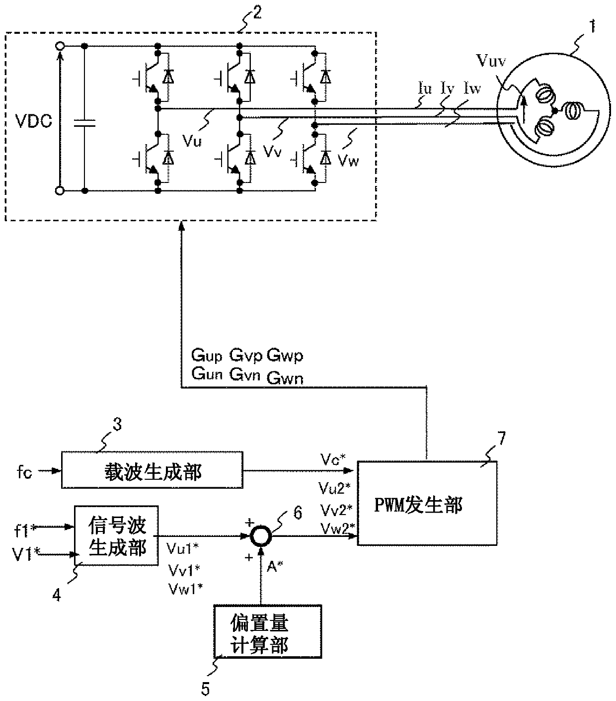
[0029] figure 1 is a configuration diagram of the motor control device in Embodiment 1, figure 2 is an element of the system. AC motor 1 is supplied with pulse voltages (U-phase pulse voltage Vu, V-phase pulse voltage Vv, W-phase pulse voltage Vw) from inverter 2, thereby flowing three-phase AC currents (U-phase current Iu, V-phase current Iv, The W-phase current Iw) is driven at the drive frequency f. Here, the voltage applied between the U-V phases of the AC motor 1 is called a line-to-line voltage Vuv.

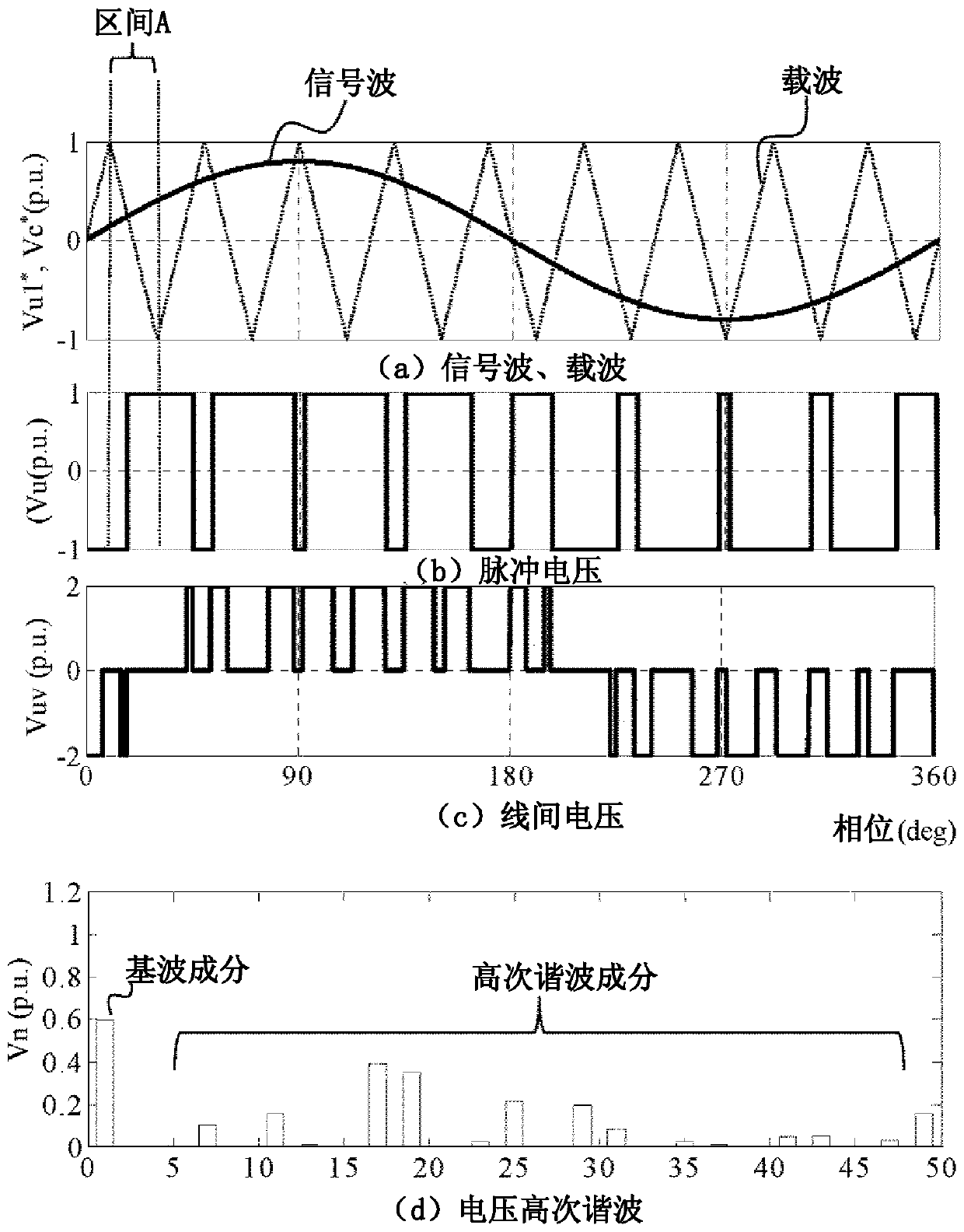
[0030] The carrier generation unit 3 generates a carrier Vc* based on the carrier frequency fc. Such as image 3 As shown in (a), the carrier Vc* is a triangular wave with amplitude 1 (normalized by half VDC / 2 of DC voltage) and frequency fc.

[0031] The signal wave generator 4 generates signal waves (U-phase signal wave Vu1 *, V-phase signal wave Vv1 *, W-phase signal wave Vw1 *) based on the frequency command f1 * and the voltage command V1 *. The signal wave is ...

Embodiment 2

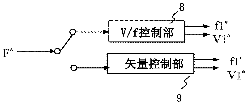
[0090] Figure 11 It is a structural diagram of Embodiment 2. This embodiment is an example in which the first embodiment is applied to the drive system of the AC motor 1 . exist Figure 11 , the description of the same parts as those in Embodiment 1 is omitted. In this embodiment, the speed command F* can be set by a higher-level device such as the computer 10 .

[0091] According to the present embodiment, high-precision speed control characteristics can be realized.


PUM


Abstract

The object of the present invention is to reduce the harmonic loss generated when an AC motor is driven with overmodulation using asynchronous PWM control without increasing the number of switching times. The motor control device includes: a signal wave generating unit that generates a signal wave based on a frequency command and a voltage command; a carrier generating unit that generates a carrier based on a carrier frequency; and a PWM generating unit that compares the signal wave with the carrier and outputs a gate signal. ; an inverter that controls a switching element based on the gate signal; and an offset amount calculation section that adds an offset amount to the signal wave, the inverter outputs a pulse voltage, the carrier frequency is fixed, and the The offset amount calculation unit adds an offset amount to the signal wave within one carrier period including voltage phases 0, 90, 180, and 270 deg, so as to fix the effective value of the fundamental wave of the pulse voltage and reduce the The effective value of the high-order harmonic of the fundamental wave is increased, and the effective value of the high-order harmonic of the lower order than the fundamental wave is added.

Description

technical field [0001] The invention relates to a motor control device and a drive system for reducing high-order harmonic loss. Background technique [0002] In a motor drive system using PWM control using an inverter, reduction of various losses is desired. The loss is divided into a loss generated by the motor (hereinafter referred to as motor loss) and a loss generated by the inverter (hereinafter referred to as inverter loss). Motor losses include losses due to fundamental wave components (hereinafter referred to as fundamental wave losses) and losses due to harmonic components (hereinafter referred to as harmonic losses). The inverter loss includes a loss caused by the on-off operation of the switching element (hereinafter referred to as switching loss) and a loss generated when the switching element is turned on (hereinafter referred to as conduction loss). [0003] Regarding the fundamental wave loss, it is reduced by adopting variable-speed driving using an invert...

Claims


Application Information

Patent Timeline
Patent Type & Authority Patents(China)
IPC IPC(8): H02P27/08
CPCH02P27/08H02P29/50
Inventor 高冈碧隅田悟士户张和明岩路善尚
Owner HITACHI IND EQUIP SYST CO LTD
Learn More