A bridge pouring facility

A bridge pouring and facility technology, applied in bridge construction, bridges, bridge materials, etc., can solve problems such as difficult to manipulate concrete, easy to overflow pit, energy consumption, etc., to reduce the workload of workers, reduce manual operations, and improve work efficiency Effect

Active Publication Date: 2019-10-15
倡创(上海)咨询管理事务所
View PDF6 Cites 0 Cited by
  • Summary
  • Abstract
  • Description
  • Claims
  • Application Information

AI Technical Summary

Problems solved by technology

[0002] In the process of bridge construction, a large amount of concrete is needed. Generally, sand, stone, water, etc. are mixed in proportion to produce concrete at the construction site. The existing concrete mixer is bulky, and because of construction needs, it is often necessary to A small amount of concrete is mixed to fill the potholes or reserved holes on the bridge road surface. At this time, the use of large concrete mixers will consume unnecessary energy and increase construction costs, and these mixers cannot be used for filling at the same time. The use of equipment has a single function. At present, the filling of the pavement mainly relies on manually filling the concrete into the pit, which is time-consuming and laborious, and it is difficult to control the amount of concrete required for filling the pit, and it is easy to overflow the pit.

Method used


Image

  • A bridge pouring facility
  • A bridge pouring facility
  • A bridge pouring facility

Examples


Embodiment Construction

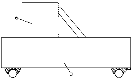
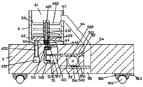
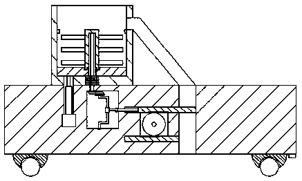
[0020] Such as Figure 1-Figure 6 As shown, a bridge pouring facility of the present invention includes a base 5 and a concrete box 6 arranged on the top left side of the base 5, the concrete box 6 is provided with a concrete cavity 61, and the concrete cavity 61 right The inner wall of the upper side is provided with an excavation opening 63, and a slide plate 62 is smoothly connected in the concrete cavity 61, and a first power device 64 is fixed in the bottom of the concrete cavity 61, and a groove is provided in the slide plate 62. hole 623, the slotted hole 623 is cooperatingly connected with a locking shaft 641 elongated up and down. The extension section at the top protrudes to the outside of the top end surface of the slide plate 62, and the outer surface is smoothly fitted with a locking stirring sleeve 621. The inner bottom of the right side of the concrete cavity 61 is provided with a downwardly elongated container 65, and the extended section at the bottom of the ...


PUM


Abstract

The invention discloses a bridge casting facility which comprises a base and a concrete tank, wherein the concrete tank is arranged at the top of the left side of the base; a concrete cavity is formed inside the concrete tank; a concrete outlet is formed in a through manner in the inner wall of the upper part of the right side of the concrete cavity; a sliding plate is connected inside the concrete cavity in smooth match; a first power device is fixedly arranged inside the bottom of the concrete cavity; a groove hole is formed inside the sliding plate; a clamping shaft which is arranged in an up and down extension manner is connected inside the groove hole in match; the extending tail end at the bottom of the clamping shaft is connected with the top of the fist power device in match; the top extending section of the clamping shaft extends outside the end surface of the top of the sliding plate; a clamping stirring sleeve is connected with the outer surface of the clamping shaft in smooth match; the bottom end of the clamping stirring sleeve is connected with the end surface of the top of the sliding plate in rotational match; an accommodation groove which is arranged extending downwards is formed in the bottom inside the right side of the concrete cavity; the extending section at the bottom of the accommodation groove extends into the base; and an oil hydraulic cylinder is fixedly arranged at the tail end of the accommodation groove. The bridge casting facility is simple in structure and convenient to operate, automatic operation and quantitative casting can be achieved, and the casting cost is lowered.

Description

technical field [0001] The invention relates to the field of bridges, in particular to a bridge pouring facility. Background technique [0002] In the process of bridge construction, a large amount of concrete is needed. Generally, sand, stone, water, etc. are mixed in proportion to produce concrete at the construction site. The existing concrete mixer is bulky, and because of construction needs, it is often necessary to A small amount of concrete is mixed to fill the potholes or reserved holes on the bridge road surface. At this time, the use of large concrete mixers will consume unnecessary energy and increase construction costs, and these mixers cannot be used for filling at the same time. The use of equipment has a single function. At present, the filling of the pavement mainly relies on manually filling the concrete into the pit, which is time-consuming and laborious, and it is difficult to control the amount of concrete required for filling the pit, and it is easy to o...

Claims


Application Information

Patent Timeline
Patent Type & Authority Patents(China)
IPC IPC(8): B28C5/16B28C7/16E01D21/00E01D101/24
Inventor 郑必达
Owner 倡创(上海)咨询管理事务所
Why Eureka
Try Eureka