Textile humidifying device

A humidification device and textile technology, applied in textiles and papermaking, equipment configuration for processing textile materials, processing of textile materials, etc., can solve problems affecting finished products, excessive humidity of textiles, and lower quality, so as to improve production quality and reduce waste , Guarantee the effect of normal humidity

Inactive Publication Date: 2017-10-17
湖州南浔贵丰纺织有限公司
View PDF0 Cites 3 Cited by
  • Summary
  • Abstract
  • Description
  • Claims
  • Application Information

AI Technical Summary

Problems solved by technology

[0002] Humidity conditions are closely related to the textile process. The textile industry uses fiber raw materials. Under different humidity conditions, their physical and mechanical properties (such as moisture regain, strength, elongation, softness and conductivity, etc.) will change. For example, when the relative humidity of cotton fiber is 60% to 70%, the dry state of the strong arm of the fiber can be increased by about 50%. This is because the cotton fiber after moisture absorption, due to The distance between molecules increases, and relative displacement will occur under the action of external force, so the elongation of fiber increases with the increase of relative humidity. Similarly, semi-finished textiles woven from fiber raw materials, before subsequent processing, their humidity It is also more important. It will affect the production of subsequent processes and directly affect the output and quality of finished products. However, after the textile is sprayed with water, its surface will absorb a large amount of water. If the surface moisture is not scraped off, it will cause Excessive humidity in textiles reduces their quality

Method used


Image

  • Textile humidifying device
  • Textile humidifying device
  • Textile humidifying device

Examples


Embodiment Construction

[0017] The following will clearly and completely describe the technical solutions in the embodiments of the present invention with reference to the accompanying drawings in the embodiments of the present invention. Obviously, the described embodiments are only some, not all, embodiments of the present invention. Based on the embodiments of the present invention, all other embodiments obtained by persons of ordinary skill in the art without making creative efforts belong to the protection scope of the present invention.

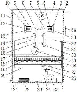
[0018] see Figure 1-3 , a textile humidifying device, comprising a housing 1, the middle end of the left side of the inner cavity of the housing 1 is fixedly connected with a first spray seat 16 through a first hollow tube 15, and the first spray seat 16 is fixedly installed at the upper left end of the inner cavity of the housing 1. Mounting base 12, the right side of the first mounting base 12 is fixedly connected with the first sleeve 10, the inner cavity ...


PUM


Abstract

The invention discloses a textile humidifying device, which comprises a casing, the middle end on the left side of the inner cavity of the casing is fixedly connected with a first spray seat through a first hollow tube, and the upper left end of the inner cavity of the casing is fixedly installed with a first spray seat. Mounting seat, the right side of the first mounting seat is fixedly connected with the first sleeve, the inner cavity of the first sleeve is movably connected with the first connecting rod through the first spring, and the upper end of the inner cavity of the housing is movably installed There is a second transmission roller, the upper right end of the inner cavity of the housing is fixedly installed with a second mount, and the left side of the second mount is fixedly connected with a second sleeve. In the present invention, the scraper is fixedly connected to the ends of the second connecting rod and the first connecting rod, and through the second spring, the second sleeve and the second mounting seat and the first spring, the first sleeve and the first mounting seat It can meet the needs of people to scrape off the moisture on the surface of the fabric, ensure the normal humidity of the fabric, and improve its production quality.

Description

technical field [0001] The invention relates to the technical field of textile equipment, in particular to a textile humidifying device. Background technique [0002] Humidity conditions are closely related to the textile process. The textile industry uses fiber raw materials. Under different humidity conditions, their physical and mechanical properties (such as moisture regain, strength, elongation, softness and conductivity, etc.) will change. For example, when the relative humidity of cotton fiber is 60% to 70%, the dry state of the strong arm of the fiber can be increased by about 50%. This is because the cotton fiber after moisture absorption, due to The distance between molecules increases, and relative displacement will occur under the action of external force, so the elongation of fiber increases with the increase of relative humidity. Similarly, semi-finished textiles woven from fiber raw materials, before subsequent processing, their humidity It is also more impor...

Claims


Application Information

Patent Timeline
Patent Type & Authority Applications(China)
IPC IPC(8): D06B1/02D06B15/08D06B23/20
CPCD06B1/02D06B15/085D06B23/20
Inventor 唐红娟
Owner 湖州南浔贵丰纺织有限公司
Why Eureka
Try Eureka