Wing type energy dissipating plate and debris flow drainage trough including same

A technology of energy-dissipating plates and row guide grooves, which is applied in construction, artificial waterways, climate change adaptation, etc., can solve problems such as easy wear and difficulty in ensuring the stability of the upper structure, so as to ensure safe use, weaken kinetic energy of movement, and weaken erosion The effect of damage

Active Publication Date: 2017-10-17
INST OF MOUNTAIN HAZARDS & ENVIRONMENT CHINESE ACADEMY OF SCI
View PDF8 Cites 5 Cited by
  • Summary
  • Abstract
  • Description
  • Claims
  • Application Information

AI Technical Summary

Problems solved by technology

[0005] In recent years, some researchers have proposed a fully-lined debris flow drainage trough (CN204728280U) for disturbing flow and dissipating energy, which is suitable for the situation where the slope of the ditch bed is large, and it can achieve the purpose of disturbing flow and dissipating energy to a certain extent. There is a problem with its structure, that is, when the regular square truss structure is used, its edges and corners are easy to wear under the impact of high bulk density debris flow, and the use of the circular truncated structure can ensure the shear resistance of the bottom and reduce wear, but due to its large bottom and top Small, and the stability of the upper structure is difficult to guarantee

Method used


Image

  • Wing type energy dissipating plate and debris flow drainage trough including same
  • Wing type energy dissipating plate and debris flow drainage trough including same
  • Wing type energy dissipating plate and debris flow drainage trough including same

Examples


Embodiment 1

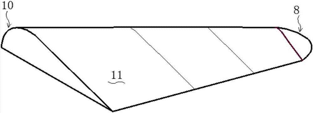
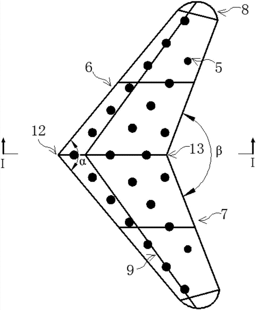
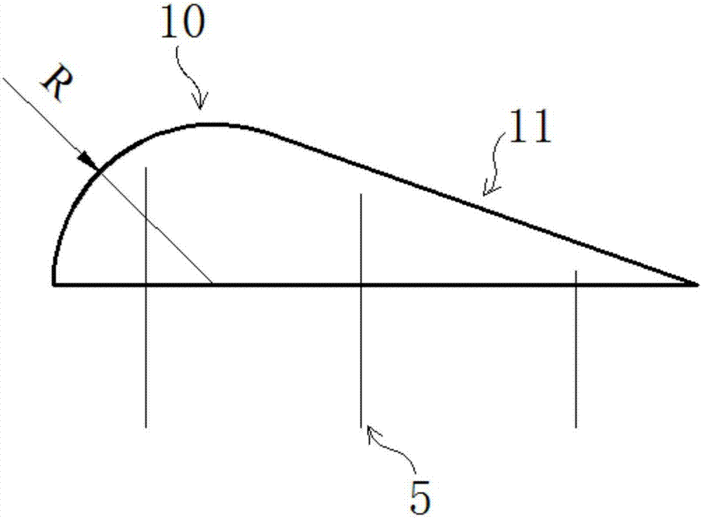
[0036] Such as Figure 1-Figure 10 shown. The drainage area of ​​a debris flow ditch is 20.4km 2 , There have been many mudslides in the channel, threatening downstream villages and farmland. In order to reduce debris flow disasters, the control measures of "blocking + drainage + silting" are adopted. Under the design standard of once in 20 years, the bulk density of debris fluid is 1.8t / m 3 , mainly transitional-viscous debris flow. In order to reduce the scouring damage of debris flow to the bottom of the rapid section of the drainage channel, the drainage measure adopts the energy dissipation and anti-scouring full-lined debris flow drainage channel of the present invention, and the flow rate of the debris flow is designed to be 50.3m 3 / s, the vertical gradient i of the drainage channel is 180‰, the planned total length of the drainage channel is 452m, of which the rapid flow section is 158m long, the bottom width B of the drainage channel is 6m, and the depth H is 5m. ...

Embodiment 2

[0039] Such as Figure 1 to Figure 9 shown. The drainage area of ​​a debris flow ditch is 3.36km 2 , The gully has repeatedly erupted in mudslides, which washed away the bridges at the mouth of the ditch and buried the road. In order to prevent debris flow from impacting bridges and silting roads, the treatment measures of "blocking + drainage + silting" are adopted. Under the design standard of once in 20 years, the bulk density of debris fluid is 2.1t / m 3 , is a viscous debris flow. In order to reduce the scouring damage of the debris flow to the bottom of the rapid section of the drainage channel, the drainage channel adopts the energy dissipation and anti-scouring full-lined debris flow drainage channel of the present invention, and the flow rate of the debris flow is designed to be 162m 3 / s, the vertical gradient i of the drainage channel is 300‰, the planned total length of the drainage channel is 186m, of which the rapid flow section is 61m long, the bottom width B ...


PUM


Abstract

The invention discloses a wing type energy dissipating plate and a debris flow drainage trough including the same, and belongs to the technical field of debris flow prevention. The wing type energy dissipating plate is of a symmetrical double-wing structure, the front side face of the wing type energy dissipating plate is an arc face, the back side face is a slope, and the arc face is in contact with the slope smoothly; the drainage trough is mainly composed of the wing type energy dissipating plates and a plurality of energy dissipating balls arranged between the wing type energy dissipating plates; and the multiple energy dissipating balls form a plurality of rhombohedra. By adoption of a combined structure of the wing type energy dissipating plates and the energy dissipating balls, energy dissipating can be conducted on the debris flow in a rapid stream for three times, so that the flow path of the debris flow can be changed, and the stability of the debris flow is influenced; and meanwhile, the existence of the wing type energy dissipating plates and the energy dissipating balls increases the roughness of the bottom of the drainage trough, so that the kinetic energy of the debris flow is weakened greatly, the effects of deceleration and energy dissipation of the debris flow in the rapid stream section are achieved, therefore the washing damage degree of the debris flow on the trough bottom is reduced, the safe utilization of the drainage trough is guaranteed, and the later maintenance cost is lowered.

Description

technical field [0001] The present invention relates to mud-rock flow prevention technology, in particular to an airfoil energy-dissipating plate and a full-lined mud-rock flow based on the combined structure of the airfoil energy-dissipating plate and energy-dissipating balls to roughen the bottom of the groove so as to realize the functions of energy dissipation, deceleration, and anti-scouring Row guide groove. Background technique [0002] Debris flow is a solid-liquid two-phase fluid full of mud, sand, stones, and boulders that occurs in valleys or slopes. It is between block gravity motions such as landslides / collapses and liquid motions such as water flows. It is laminar or The state of turbulent flow movement has the characteristics of sudden outbreak, fast movement speed and short duration. my country is one of the countries with the most severe debris flow disasters in the world. There are many types of disasters, wide distribution, intense activities, and serious...

Claims


Application Information

Patent Timeline
Patent Type & Authority Applications(China)
IPC IPC(8): E02B5/08E02B5/00
CPCE02B5/00E02B5/08Y02A30/60
Inventor 方迎潮王道杰何松膛洪勇苏凤环
Owner INST OF MOUNTAIN HAZARDS & ENVIRONMENT CHINESE ACADEMY OF SCI
Why Eureka
Try Eureka