Finite element analysis method based on composite layers for small-sized throwing-type unmanned aerial vehicle

A technology of composite materials and analysis methods, applied in the field of finite element analysis of drones, can solve problems such as prolonging the development cycle, poor analysis accuracy, and high cost, and achieve the effects of reducing quantity, improving analysis accuracy, and large economic benefits

Inactive Publication Date: 2017-10-17
中科机器人科技有限公司
View PDF7 Cites 16 Cited by
  • Summary
  • Abstract
  • Description
  • Claims
  • Application Information

AI Technical Summary

Problems solved by technology

[0006] However, the above existing technologies have relatively poor analysis accuracy, cannot guarantee buckling instabi

Method used


Image

  • Finite element analysis method based on composite layers for small-sized throwing-type unmanned aerial vehicle
  • Finite element analysis method based on composite layers for small-sized throwing-type unmanned aerial vehicle
  • Finite element analysis method based on composite layers for small-sized throwing-type unmanned aerial vehicle

Examples


Embodiment 1

[0032] (1) Calculation process and results of ultimate strength:

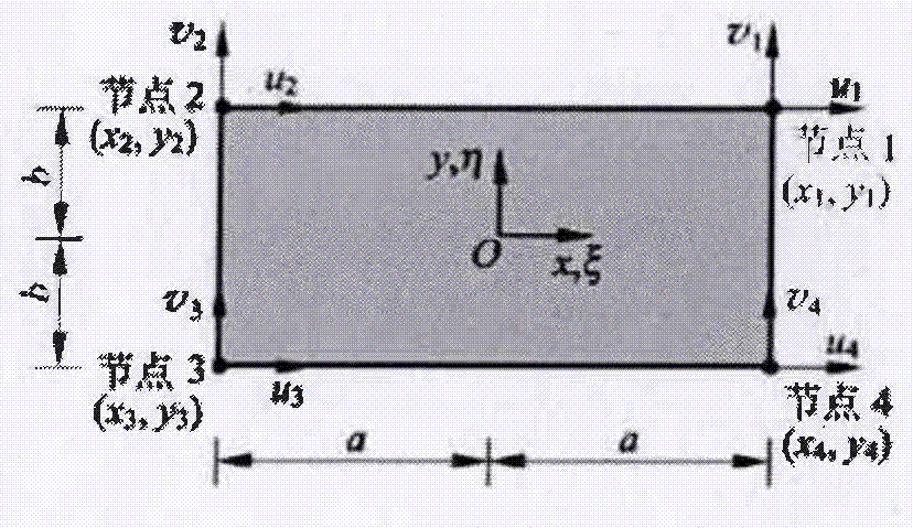
[0033] The finite element ultimate strength calculation is mainly to obtain the displacement of each node and the stress and strain of each unit, and compare it with the required stress of the composite material to determine whether the composite material can withstand the applied load.

[0034] Analyze the stress situation at any point of each unit of the finite element, and decompose along the coordinate axis directions x, y, z to obtain a balanced differential equation:

[0035]

[0036] σ i is the stress that the unit bears on the i axis (i is the x, y, z axis); τ ij is the shear stress borne by the unit in the ij plane (i, j are x, y, z axes); F i is the external load that the unit bears in the i direction (i is the x, y, z axis).

[0037] Assuming that the unit has a small displacement and a small deformation under the stress state, the relationship between the strain vector and the displacement vec...


PUM

PropertyMeasurementUnit
Thicknessaaaaaaaaaa

Abstract

The invention discloses a finite element analysis method based on composite layers for a small-sized throwing-type unmanned aerial vehicle, aims at disclosing an emulation method of composite layers, and solves calculation of ultimate strength and flexion of the small-sized throwing-type unmanned aerial vehicle during the primary design stage. The finite element analysis method comprises the steps of (1) building a finite-element network model of the small-sized throwing-type unmanned aerial vehicle; (2) building a property database of the composite materials, and designing a primary layer paving scheme of the composite materials; (3) analyzing the cruise state of the unmanned aerial vehicle, designing reasonable boundary conditions, conducting bearing load, and emulating the ultimate strength and structural flexion stability of each section and each layer of the unmanned aerial vehicle; (4) according to the calculation result in (3), analyzing whether or not the ultimate strength and the structural flexion stability of each section and each layer satisfy the design demands, and redesigning thickness and angles of the composite layers, wing rib structures and wing rib locations by refining grid density to satisfy the design demands. The finite element method based on the composite layers for the small-sized throwing-type unmanned aerial vehicle can effectively reduce the quantity of testing pieces of composite components, and shortening the preparation period.

Description

technical field [0001] The invention relates to a finite element analysis of an unmanned aerial vehicle, in particular to realize the simulation of a composite material layup of a small unmanned aerial vehicle, and the calculation of ultimate strength and buckling stability. Background technique [0002] Composite materials are characterized by strong anisotropy and designability. Only by optimizing the design according to the structural characteristics can the design requirements be met more efficiently. For metal structures, due to the isotropic characteristics, the optimization analysis of rib position, form and thickness can be completed at the same time, while for composite materials, due to the anisotropic characteristics, the structural form is laid layer by layer , the angle of each layer may be different, and it is impossible to directly analyze the position and form of the ribs, as well as the angle and thickness of the ply. After the reinforcement is laid out, th...

Claims


Application Information

Patent Timeline
IPC IPC(8): G06F17/50
CPCG06F30/15G06F30/23G06F2111/04G06F2113/28
Inventor 丁志超王飞陈长兴
Owner 中科机器人科技有限公司
Why Eureka
Try Eureka