
Accumulator system for accumulating electrical energy

A storage system, a technology for storing electrical energy, applied in the field of storage systems, to achieve the effect of preventing damage

Inactive Publication Date: 2017-10-17
SIEMENS AG
View PDF10 Cites 0 Cited by
  • Summary
  • Abstract
  • Description
  • Claims
  • Application Information

AI Technical Summary

Problems solved by technology

Here, there is a DC voltage intermediate circuit between the energy store and the inverter, in which overvoltages can occur

Method used


Image

  • Accumulator system for accumulating electrical energy
  • Accumulator system for accumulating electrical energy

Examples


Embodiment Construction

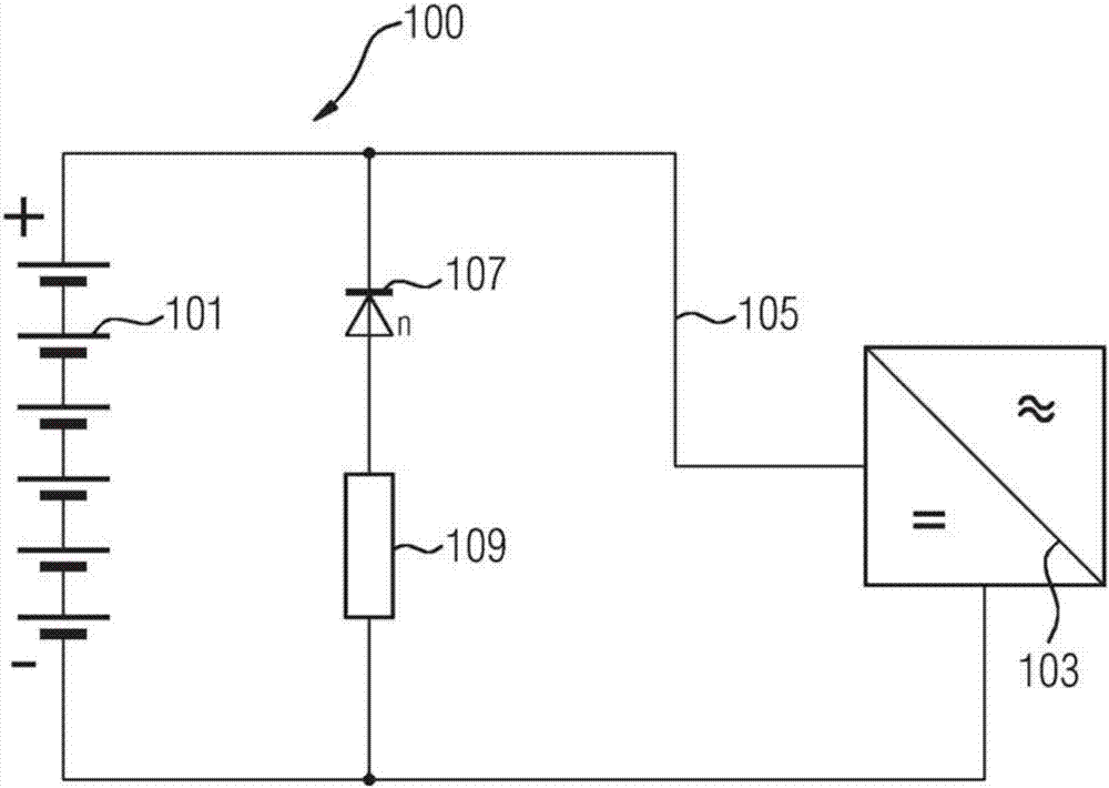
[0021] figure 1 A view of a storage system 100 for storing electrical energy is shown. The storage system 100 comprises: an energy store 101 for generating a direct voltage; a converter 103 for converting the direct voltage into an alternating voltage, which is connected to the energy store 101 via an intermediate circuit 105; and a diode 107, which is in the intermediate circuit 105 Connected in parallel in the opposite direction to the energy store 101 and the converter 103 for limiting the voltage in the intermediate circuit 105 . A converter is, for example, an inverter for converting a direct voltage into an alternating voltage. A parallel circuit of diodes 107 is thus formed in the reverse direction in intermediate circuit 105 of energy store 101 and converter 107 .

[0022] The energy store 101 can be a mechanical, electrical, electrochemical, chemical energy store or thermal store. The mechanical energy store is, for example, a flywheel, a pumped hydro storage plant...


PUM

PropertyMeasurementUnit
Resistanceaaaaaaaaaa

Abstract

The present invention relates to an accumulator system (100) for accumulating electrical energy, comprising an energy accumulator (101) for generating a direct voltage; a converter (103) for converting the direct voltage into an alternating voltage, which is connected to the energy accumulator (101) via a DC link (105); and a diode (107) which is connected in parallel with the energy accumulator (101) and the converter (103) with reverse bias so as to limit a voltage in the DC link (105).

Description

technical field [0001] The invention relates to a storage system for storing electrical energy. Background technique [0002] The ever-increasing demands placed on storage systems require high safety standards during operation as well as protection mechanisms against failure situations. The connection of the energy store as a DC voltage source or DC voltage sink to the AC grid takes place via an inverter. In this case, there is a direct voltage intermediate circuit between the energy store and the inverter, in which overvoltages may occur. [0003] Current methods for protecting intermediate circuits, energy stores and inverters use contactors, which open in the event of a fault. These contactors are electrically controlled by a controller with suitable software and are triggered when a certain voltage level is exceeded to prevent damage to the inverter and energy storage. Contents of the invention [0004] The technical problem addressed by the present invention is to ...

Claims


Application Information

Patent Timeline
IPC IPC(8): H02M1/32H02M5/458
CPCH02M1/32H02M5/458H02M1/327H02M7/46
Inventor C.贝特津J.J.拉伯斯H.沃尔夫施密特
Owner SIEMENS AG
Learn More