
Shearing knife with bionic curved surface

A technology of shearing knives and curved surfaces, used in shearing devices, tools for shearing machines, metal processing equipment, etc. The effect of improving the characteristics, increasing the number of times of use, and reducing wear and tear

Active Publication Date: 2017-10-20
JILIN UNIV
View PDF6 Cites 2 Cited by
  • Summary
  • Abstract
  • Description
  • Claims
  • Application Information

AI Technical Summary

Problems solved by technology

At present, factories and scrap steel processing cannot replace a large number of blades every year. Not only the cost of blades increases, but also the production time is limited, which greatly reduces the output value and affects the entire processing efficiency.

Method used


Image

  • Shearing knife with bionic curved surface
  • Shearing knife with bionic curved surface
  • Shearing knife with bionic curved surface

Examples


Embodiment 1

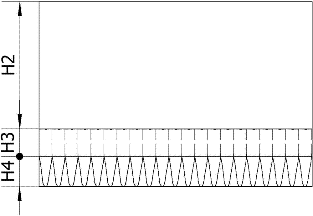
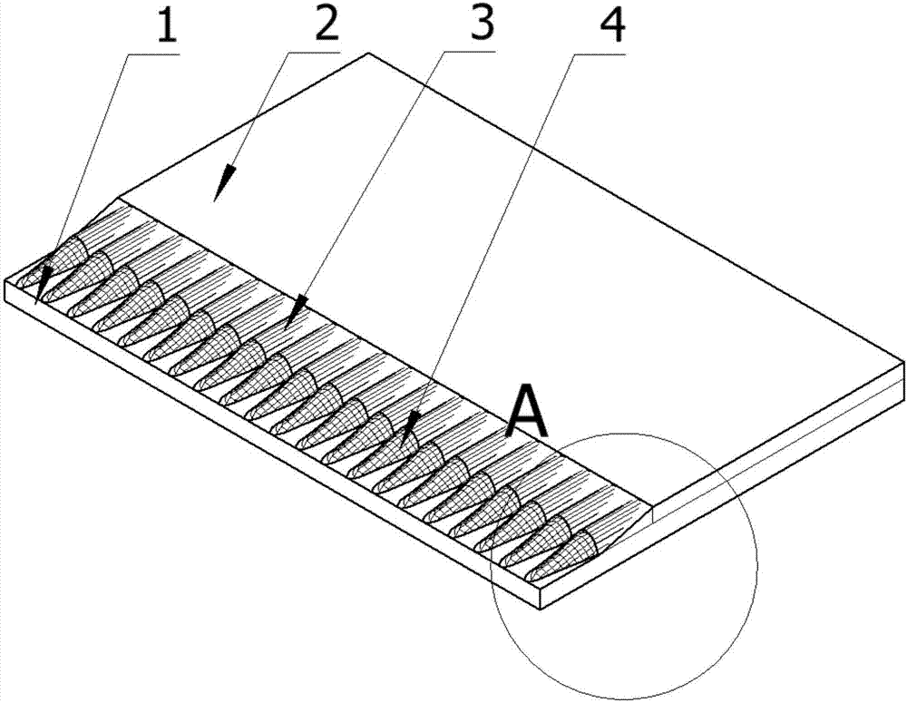
[0030] see figure 1 , figure 2 , image 3 , Figure 4 , Figure 5 and Figure 6 As shown, this embodiment includes a knife base 1, a knife back 2, a transition section 3 and a knife tip 4, the transition section 3 is composed of a bionic semi-cylinder 5 and a triangular prism 6, and the knife base 1 is used as the back of the entire bionic shearing knife to carry the knife back 2. The transition section 3 and the knife tip 4; the knife back 2 is located on the surface of the knife base 1, and the bottom surface and two sides of the knife back 2 coincide with the bottom surface and the side surfaces of the knife base 1; the transition section 3 is a bionic half cylinder 5 and a triangular prism 6 structure Assembled body, the bottom of triangular prism 6 coincides with the top of knife back section, and the length and width of bottom surface are identical with knife back section, and the upper part of semi-bionic cylinder 5 coincides with triangular prism body.

[0031] T...

Embodiment 2

[0044] see figure 1 , figure 2 , image 3 , Figure 4 , Figure 5 and Figure 6 As shown, this embodiment includes a knife base 1, a knife back 2, a transition section 3 and a knife tip 4, the transition section 3 is composed of a bionic semi-cylinder 5 and a triangular prism 6, and the knife base 1 is used as the back of the entire bionic shearing knife to carry the knife back 2. The transition section 3 and the knife tip 4; the knife back 2 is located on the surface of the knife base 1, and the bottom surface and two sides of the knife back 2 coincide with the bottom surface and the side surfaces of the knife base 1; the transition section 3 is a bionic semi-cylindrical body 5 and a triangular prism 6 Structural composite body, the bottom of triangular prism 6 coincides with the top of knife back section, and the length and width of triangular prism 6 bases are identical with knife back section, and the upper part of semi-bionic cylinder 5 coincides with triangular pris...


PUM


Abstract

The invention discloses a shearing knife with a bionic curved surface and belongs to the technical field of metal cutting. The shearing knife with the bionic curved surface is composed of a knife matrix, a knife back, a transition segment and a knife point; and the transition segment is composed of bionic semi-cylinders and a triangular prism. The knife matrix is of a cuboid structure and serves as the back side of the whole bionic shearing knife to bear the knife back, the transition segment and the knife point; the knife back is a cuboid, and is located on the surface of the knife matrix, and the bottom face and the two side faces of the knife back coincide with the bottom face and the side faces of the knife matrix correspondingly; the transition segment is a combination of the bionic semi-cylinders and the triangular prism structure; and the bionic semi-cylinders are closely arranged in an array manner in the long side direction of the shearing knife. The bottom of the triangular prism coincides with the top end of the rear segment of the knife, and the length and the width of the bottom face of the triangular prism are equal to those of the rear segment of the knife; the upper portions of the bionic semi-cylinders coincide with the triangular prism; and the knife point is a bionic curved surface structure. By means of the shearing knife with the bionic curved surface, the shearing capacity of blades of a shearing machine can be improved, the blade utilizing time is prolonged, the work efficiency is improved, and cost is reduced.

Description

technical field [0001] The invention belongs to the technical field of metal cutting, and in particular relates to a bionic curved surface shearing knife. Background technique [0002] The shearing machine is the main equipment in the cutting device of the modern factory, and the gantry shearing machine is mainly used in scrap steel cutting and large-size cutting. In the iron and steel industry, shearing machines are used more and more, and more are used for heavy cutting. [0003] The blade of the shearing machine is the most critical part of the shearing machine. Its performance is related to the use and efficiency of the entire equipment, and is closely related to production and processing and economic benefits. At present, factories and scrap steel processing cannot replace a large number of blades every year. Not only the cost of blades increases, but also the production time is limited, which greatly reduces the output value and affects the entire processing efficienc...

Claims


Application Information

Patent Timeline
Patent Type & Authority Applications(China)
IPC IPC(8): B23D35/00
CPCB23D35/001
Inventor 马云海王慧鑫陈创发禹江涛齐红岩
Owner JILIN UNIV
Learn More