Bionic curved surface shear knife

A technology of shearing knives and curved surfaces, used in shearing devices, tools for shearing machines, maintenance and safety accessories, etc., can solve the problems of easy wear and large tool load, etc.

Inactive Publication Date: 2021-05-18
HUZHOU TEACHERS COLLEGE
View PDF1 Cites 0 Cited by
  • Summary
  • Abstract
  • Description
  • Claims
  • Application Information

AI Technical Summary

Problems solved by technology

[0004] However, the shearing knife of the above design is only designed with one knife for shearing, and the knife load is relatively large, and it is relatively easy to wear. On the other hand, the force on the knife tip is relatively concentrated and not well dispersed.

Method used


Image

  • Bionic curved surface shear knife
  • Bionic curved surface shear knife
  • Bionic curved surface shear knife

Examples


Embodiment 1

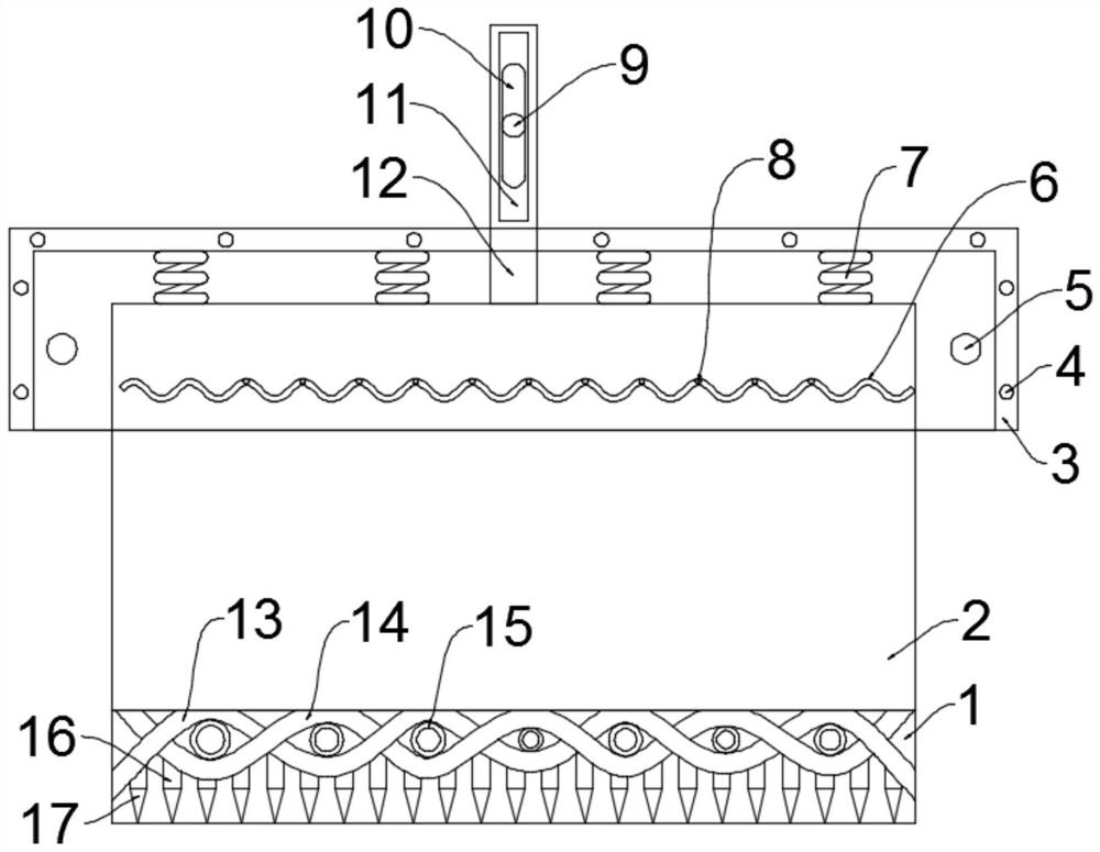
[0027] see Figure 1~4 , in an embodiment of the present invention, a bionic curved surface shearing knife includes a knife body and an installation shell 3 for installing the knife body, the installation shell 3 is arranged on the top of the knife body, and the knife body is composed of two symmetrically arranged The tool splicing structure, further, the tool includes a knife base 1, a knife back 2 and a knife tip 17, the knife base 1 is provided with a knife back 2 on the outer wall, and the three sides of the knife back 2 are on the same level as the corresponding sides of the knife base 1. Qi, the first bionic snake-shaped strip 13 and the second bionic snake-shaped strip 14 are fixed on the knife base 1 below the knife back 2, and the first bionic snake-shaped strip 13 and the second bionic snake-shaped strip 14 are far away from the knife base 1. The surface is a curved surface, and the first bionic snake-shaped strip 13 and the second bionic snake-shaped strip 14 are al...

Embodiment 2

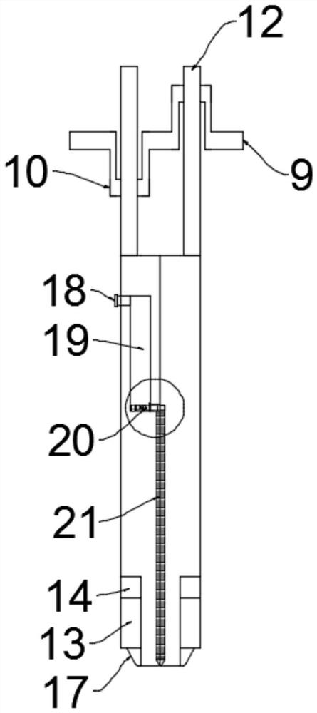
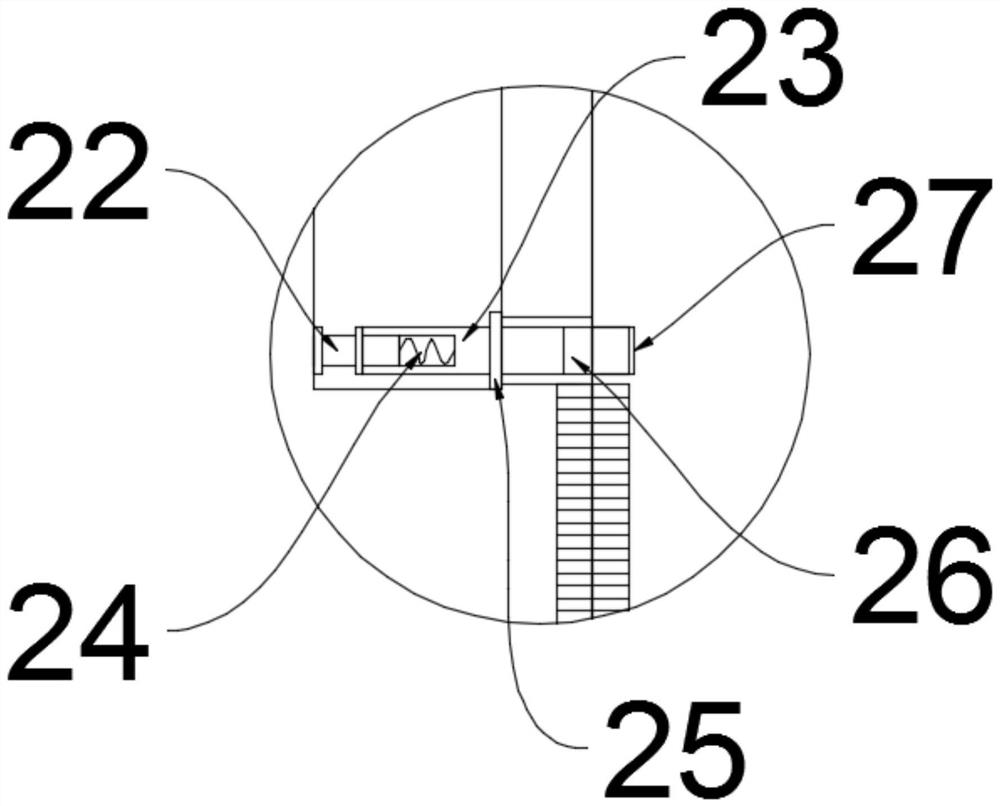
[0032] see Figure 5 The difference between the embodiment of the present invention and embodiment 1 is that in order to make the lubricating oil fully distributed in the length space of the entire tool, the bottom of both ends of the installation shell 3 are fixed with a shell 28, and the inside of the shell 28 A piston 31 is provided, and a push rod is fixed on one side of the piston 31 close to the cutter body. The push rod penetrates the housing 28 and contacts the side wall of the cutter body. The other side of the piston 31 and the inner wall of the housing 28 A third spring 29 is fixedly connected, and a hose 30 is connected to the side wall of the casing 28 close to the cutter body. The hose 30 is connected to the cutter body and communicates with the top of the adjacent oil flow groove 21, and the adjacent oil flow groove 21 They are connected through communication holes. When the cutter body reciprocates, the piston 31 is driven to reciprocate left and right by the p...


PUM


Abstract

The invention discloses a bionic curved surface shear knife which comprises a knife body and a mounting shell used for mounting the knife body, the mounting shell is arranged at the top of the knife body, the knife body is formed by splicing two symmetrically-arranged cutters, each cutter comprises a knife base body, a knife back and a knife point, and a first bionic snakelike strip and a second bionic snakelike strip are fixed to the positions, below the knife back, of the knife base body; and the first bionic snakelike strip and the second bionic snakelike strip are arranged in a staggered winding mode, a motor is fixedly installed on the upper surface of the mounting shell, a crankshaft is fixedly installed on an output shaft of the motor, two connecting rod journals are arranged on the crankshaft at intervals, the two connecting rod journals are matched with two driving rods correspondingly, and the knife body and the mounting shell for mounting the knife body are arranged, so that force transmitted by the knife point and a transition section can be fully and uniformly dispersed, and the mechanical property is improved; and a driving rod, the crankshaft, the connecting rod journals, a wave-shaped groove and a protrusion are arranged, the two cutters are driven to reciprocate in a left-right staggered mode, the two cutters vibrate up and down when moving left and right, and the shearing efficiency is improved.

Description

technical field [0001] The invention relates to the technical field of metal cutting, in particular to a bionic curved surface shearing knife. Background technique [0002] The blade of the shearing machine is the most critical part of the shearing machine. Its performance is related to the use and efficiency of the entire equipment, and is closely related to production and processing and economic benefits. At present, factories and scrap steel processing cannot replace a large number of blades every year. Not only the cost of blades increases, but also the production time is limited, which greatly reduces the output value and affects the entire processing efficiency. [0003] Chinese invention patent CN107262812A discloses a bionic curved surface shearing knife, which belongs to the field of metal cutting technology and consists of a knife base, a knife back, a transition section and a knife tip; the transition section is composed of a bionic semi-cylinder and a triangular ...

Claims


Application Information

Patent Timeline
Patent Type & Authority Applications(China)
IPC IPC(8): B23D35/00B23Q11/10B23Q5/027
CPCB23D35/001B23Q5/027B23Q11/10
Inventor 张清珠徐宝库魏玉兰李兵
Owner HUZHOU TEACHERS COLLEGE
Why Eureka
Try Eureka