Coarse grinding device

A technology of grinding rods and placing blocks, which is applied in the field of mechanical processing, can solve the problems of low efficiency, difficult handling, easy to scratch workers, etc., and achieve the effect of reducing equipment failure and fewer structural parts

Inactive Publication Date: 2017-10-20
孟卫兵
View PDF0 Cites 3 Cited by
  • Summary
  • Abstract
  • Description
  • Claims
  • Application Information

AI Technical Summary

Problems solved by technology

At present, the most used method is to remove burrs by manual grinding, but the manual deburring method cannot meet the corresponding requirements for burr size and burr uniformity, and it is easy to scratch workers, and the efficiency is low,...

Method used


Image

  • Coarse grinding device
  • Coarse grinding device
  • Coarse grinding device

Examples


Embodiment Construction

[0018] The present invention will be further described below in conjunction with the accompanying drawings.

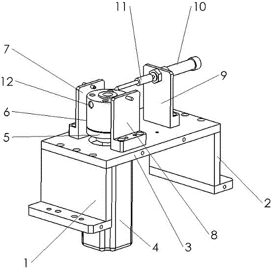
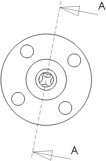
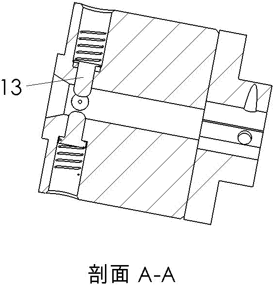
[0019] Such as figure 1 , figure 2 , image 3 As shown, a rough grinding device includes a first support plate 1, a second support plate 2 is arranged behind the first support plate 1, and a second support plate 2 is arranged above the first support plate 1 and the second support plate 2 Bottom plate 3, the lower surface of the bottom plate 3 is provided with a rotating motor 4, the rotating motor 4 is used to accurately move the hole to the grinding position, the upper end of the rotating motor 4 is provided with a connecting plate 5, and the upper end of the connecting plate 5 is provided with a Block 6, a step hole is provided in the placement block 6 to limit the height of the workpiece. The left side of the placement block 6 is provided with a first vertical board 7, and the right side is symmetrically provided with a second vertical board 8. The placement Blo...


PUM


Abstract

The invention discloses a rough grinding device, which comprises a first support plate, a second support plate is arranged behind the first support plate, a bottom plate is arranged above the first support plate and the second support plate, and a rotating motor is arranged on the lower surface of the bottom plate. The upper end of the rotating motor is provided with a connecting plate, the upper end of the connecting plate is provided with a placement block, the left side of the placement block is provided with a first vertical plate, the right side is symmetrically provided with a second vertical plate, the rear of the placement block is provided with a cylinder mounting plate, and behind the cylinder mounting plate The part on the surface is provided with a polishing cylinder, the front end of the polishing cylinder is provided with a polishing rod, and the side walls around the block are provided with a pressure rod mounting hole, and a pressure rod is provided in the pressure rod mounting hole; in general, the present invention has the advantages of simple structure, easy use The advantages of convenience, small size and easy handling.

Description

technical field [0001] The invention relates to the technical field of machining, in particular to a rough grinding device. Background technique [0002] The burrs generated during the manufacturing process of mechanical parts have adverse effects on many aspects such as the accuracy, use, reprocessing positioning, operation safety and appearance quality of the parts. At the same time, since deburring takes a lot of time and cost, it has also become one of the obstacles to reducing the production cost of parts, so sufficient attention should be paid to deburring. In the process of inner hole processing, after the hole processing is completed, there are certain burrs, and the hole needs to be simply rough ground before the next process. At present, the most used method is to remove burrs by manual grinding, but the manual deburring method cannot meet the corresponding requirements for burr size and burr uniformity, and it is easy to scratch workers, and the efficiency is low...

Claims


Application Information

Patent Timeline
IPC IPC(8): B23D67/04B23D69/00B23Q3/06B23Q7/02
CPCB23D67/04B23D69/00B23Q3/06B23Q7/02
Inventor 孟卫兵
Owner 孟卫兵
Why Eureka
Try Eureka