
Marking method and marking device

A laser and beam expander technology, applied in metal processing equipment, welding equipment, manufacturing tools, etc., can solve the problems of low assembly accuracy of electronic products, shell stress deformation, low flatness, etc., to achieve good conductivity and improve destructive power , the effect of increasing power density

Inactive Publication Date: 2017-10-20
HANS LASER TECH IND GRP CO LTD +1
View PDF4 Cites 3 Cited by
  • Summary
  • Abstract
  • Description
  • Claims
  • Application Information

AI Technical Summary

Problems solved by technology

[0004] Based on this, it is necessary to provide a marking method and its device for the problems of stress deformation, low flatness, and even low assembly accuracy of electronic products after removing the anodized aluminum shell.

Method used

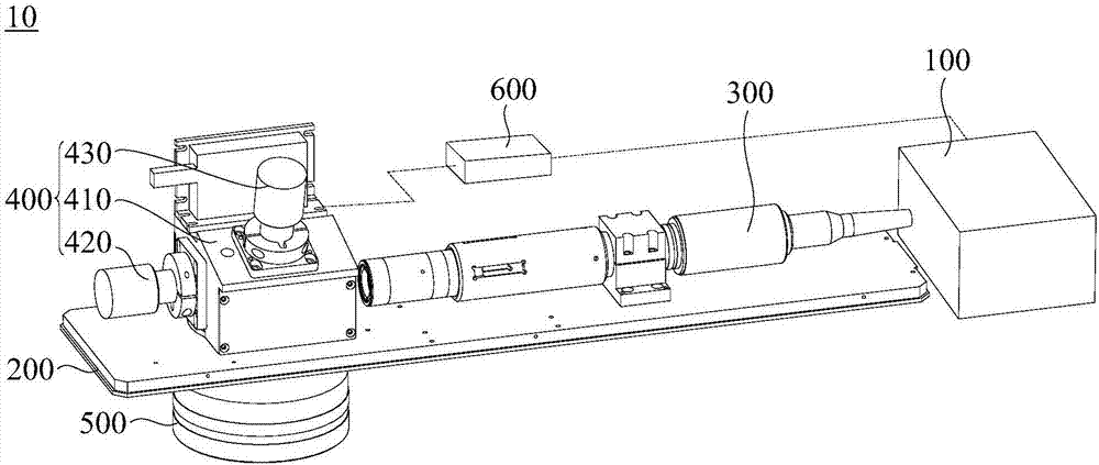
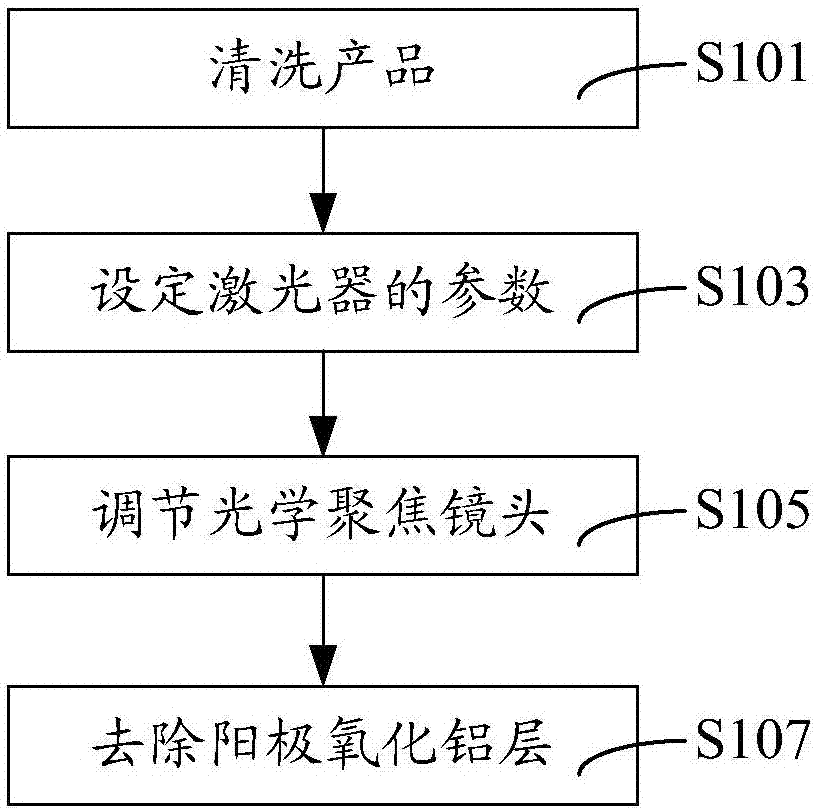
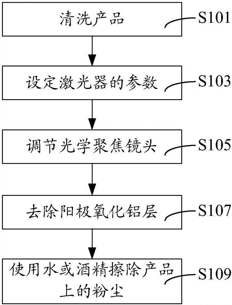

Image

  • Marking method and marking device
  • Marking method and marking device
  • Marking method and marking device

Examples


Embodiment Construction

[0032] In order to facilitate the understanding of the present invention, the marking method and its device will be described in a more comprehensive manner with reference to the relevant drawings. The first embodiment of the marking method and its device is shown in the attached drawings. However, the marking method and its device can be implemented in many different forms and are not limited to the embodiments described herein. On the contrary, the purpose of providing these embodiments is to make the disclosure of the marking method and its device more thorough and comprehensive.

[0033] It should be noted that when an element is referred to as being "fixed to" another element, it can be directly on the other element or a central element may also exist. When an element is considered to be "connected" to another element, it can be directly connected to the other element or an intermediate element may be present at the same time. The terms "vertical", "horizontal", "left", "r...


PUM

PropertyMeasurementUnit
Pulse widthaaaaaaaaaa

Abstract

The invention relates to a marking method and a marking device. The marking device is used for removing anodic aluminum oxide on a product. The marking device comprises a laser, a fixed seat, a beam expander, a galvanometer and a focusing lens; the laser is used for generating a laser beam; the fixed seat is provided with a through hole; the beam expander is arranged on the fixed seat, is opposite to the laser, and is used for enlarging the diameter of the laser beam; the galvanometer is arranged on the fixed seat, and is close to the beam expander; the galvanometer is used for deflecting the laser beam output by the beam expander, so as to allow the laser beam to pass the through hole; and the focusing lens is arranged on the fixed seat, is located on one side, departing from the galvanometer, of the fixed seat, and corresponds to the through hole. According to the marking method and the marking device, the laser beam generated by the laser is subjected to combined action of the beam expander and the focusing lens, and then the power density of the laser beam acting on the surface of the product is increased substantially, so that a situation that no product after being marked generates stress deformation is ensured, and the product has good conductivity.

Description

Technical field [0001] The present invention relates to the technical field of laser processing, in particular to a marking method and device. Background technique [0002] Anodized aluminum refers to the plating of a dense layer of aluminum oxide on the surface of aluminum or aluminum alloy to prevent oxidation of aluminum or aluminum alloy. Although the chemical properties of anodized aluminum oxide are the same as those of aluminum oxide formed by natural oxidation, the corrosion resistance, wear resistance and decoration of anodized aluminum oxide are better than those of aluminum oxide formed by natural oxidation. [0003] Traditional electronic products use anodized aluminum shells, such as mobile phones, tablets, and laptops. In order to reduce weight and volume, the thickness of the housing of the electronic product is less than or equal to 0.7 mm. Since the inner surface of the housing of the electronic product has electrical conductivity requirements, but the anodized a...

Claims


Application Information

Patent Timeline
IPC IPC(8): B23K26/362B23K26/064B23K26/142
CPCB23K26/064B23K26/142B23K26/361
Inventor 温延台洪剑锋范醉风叶天茂吴俊水李鹤吴烈高云峰
Owner HANS LASER TECH IND GRP CO LTD
Learn More