
Positioning clamp applied to automatic welding equipment for inner seams of drive axle housing rear cover

A technology of drive axle housing and welding equipment, applied in welding equipment, auxiliary welding equipment, welding/cutting auxiliary equipment, etc. Cleaning and other issues, to achieve good practical results and commercial value, reduce the workload of adjustment, and achieve the effect of simple structure

Pending Publication Date: 2017-10-20
CHENGDU HANYAN TECH
View PDF7 Cites 1 Cited by
  • Summary
  • Abstract
  • Description
  • Claims
  • Application Information

AI Technical Summary

Problems solved by technology

[0004] 1) Welding quality problems caused by unclean workpiece surface or welding torch angle deviation;
[0005] 2) Welding quality problems caused by unreasonable welding process parameters;
[0006] 3) Welding quality problems caused by the inconcentricity of the workpiece reinforcement ring and the back cover;
Therefore, in view of the above problems, the automatic welding equipment for the inner seam of the rear cover of the drive axle case is designed. The automatic welding equipment for the inner seam of the rear cover of the drive axle case needs to position the rear cover of the drive axle case during welding, and the positioning is required to be accurate and guaranteed. The concentricity between the inner seam position of the back cover and the back cover, the existing equipment cannot meet this requirement

Method used


Image

  • Positioning clamp applied to automatic welding equipment for inner seams of drive axle housing rear cover
  • Positioning clamp applied to automatic welding equipment for inner seams of drive axle housing rear cover
  • Positioning clamp applied to automatic welding equipment for inner seams of drive axle housing rear cover

Examples


Embodiment Construction

[0029] The present invention will be further described below with reference to the accompanying drawings and examples, and the implementation of the present invention includes but not limited to the following examples.

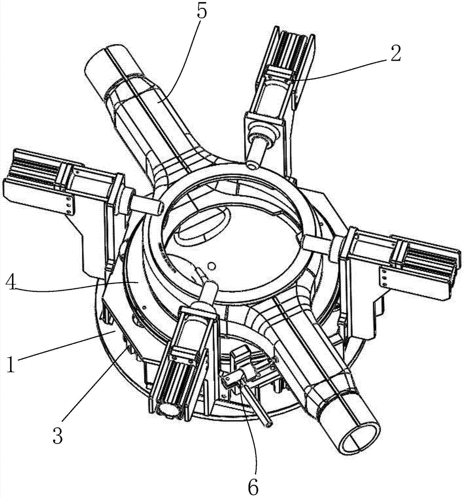
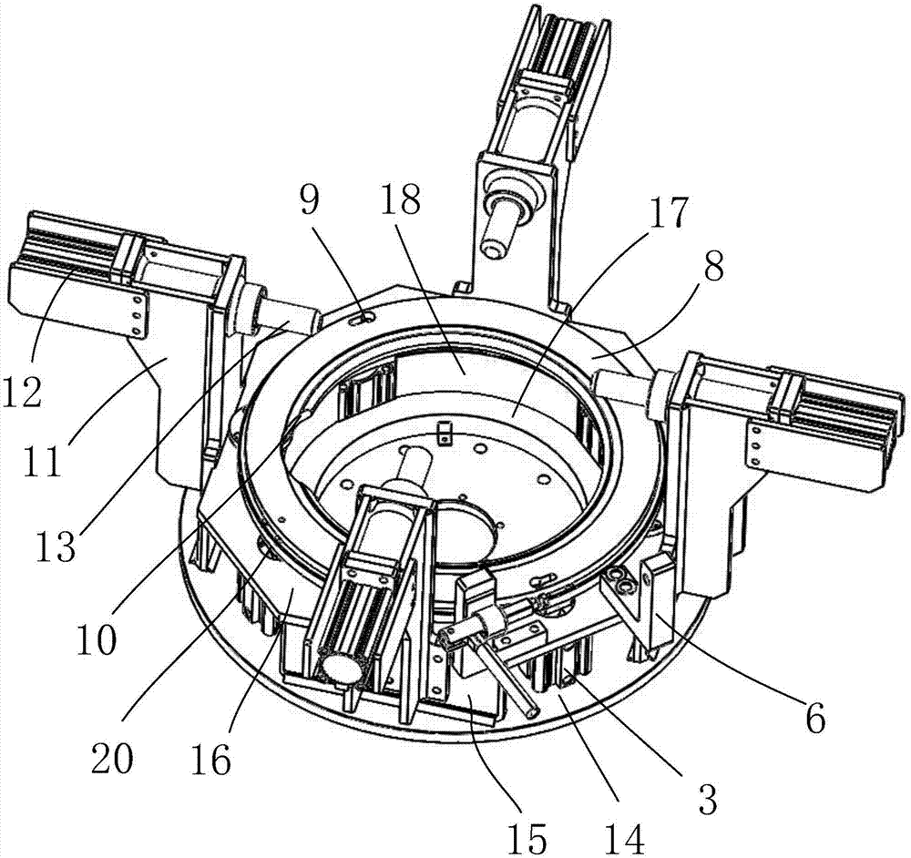
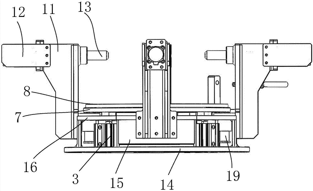
[0030] Such as Figure 1~3 As shown, the positioning fixture applied to the automatic welding equipment for the rear cover of the drive axle housing includes a base 1, a positioning cylinder assembly 2, a jacking cylinder 3, a rear cover positioning ring assembly 4, and a fixing mechanism 6; wherein, the rear cover positioning ring The assembly 4 includes an annular support ring 7 connected to the piston rods of the four jacking cylinders 3, and an annular positioning plate 8 arranged on the support ring 7 for positioning the rear cover 5 of the drive axle case; the positioning cylinder assembly 2 includes fixing with the base 1 The connected cylinder support arm 11, the cylinder 12 arranged on the cylinder support arm 11, the positioning shaft 13 connected wi...


PUM


Abstract

The invention discloses a positioning clamp applied to automatic welding equipment for inner seams of a drive axle housing rear cover. The positioning clamp comprises a base, four positioning air cylinder assemblies which are fixedly mounted on the base and are uniformly distributed along the periphery of the base, four jacking air cylinders, a rear cover positioning ring assembly arranged on the base, and a fixing mechanism arranged on the base for preliminarily fixing the drive axle housing rear cover; axle centers of the four positioning air cylinder assemblies are at equal altitude for guaranteeing height of the inner seams of the drive axle housing rear cover to be consistent; the rear cover positioning ring assembly is used for guaranteeing positions of the inner seams of the drive axle housing rear cover and concentricity of the rear cover; and the four jacking air cylinders and the four positioning air cylinder assemblies are arranged in a spaced mode. The positioning clamp is reasonable in design, is simple in structure, can be used for clamping and positioning the drive axle housing rear cover, realizes manual workpiece loading and unloading, automatically positions and clamps the workpieces, meets consistency of positions of welding seams of the rear cover after the workpieces are clamped, and has a very good practical effect and a very good commercial value.

Description

technical field [0001] The invention relates to the field of automatic welding equipment for the inner seam of the rear cover of the drive axle case, in particular to a positioning fixture applied to the automatic welding equipment for the inner seam of the rear cover of the drive axle case. Background technique [0002] In medium and heavy vehicles, the drive axle housing is the carrier that supports the load of the vehicle, bears the reaction force and moment from the road surface transmitted by the wheels, and transmits it to the frame (or body) through the suspension. It plays an important role, and its manufacturing quality has a direct impact on the quality of the whole bridge and even the whole vehicle. The oil leakage and oil seepage phenomenon of the welding seam of the rear cover of the drive axle has always been one of the common problems in the manufacture of the axle housing. Due to oil leakage and oil leakage from the welding seam of the rear cover of the axle...

Claims


Application Information

Patent Timeline
Patent Type & Authority Applications(China)
IPC IPC(8): B23K37/04
CPCB23K37/0443B23K37/0461
Inventor 李林
Owner CHENGDU HANYAN TECH
Learn More