Evaporation source device used for evaporation

An evaporation source and evaporation technology, which is used in vacuum evaporation coating, sputtering coating, ion implantation coating, etc. The effect of plugging holes

Active Publication Date: 2017-10-20
WUHAN CHINA STAR OPTOELECTRONICS SEMICON DISPLAY TECH CO LTD
View PDF5 Cites 1 Cited by
  • Summary
  • Abstract
  • Description
  • Claims
  • Application Information

AI Technical Summary

Problems solved by technology

[0006] In view of the deficiencies in the prior art, the present invention provides an evaporation source device for evaporation, which can solve the problem of clogging of the evaporation holes of the evaporation crucible without opening the vacuum chamber

Method used


Image

  • Evaporation source device used for evaporation
  • Evaporation source device used for evaporation
  • Evaporation source device used for evaporation

Examples


Embodiment 1

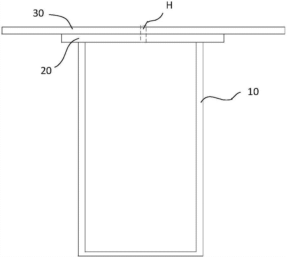
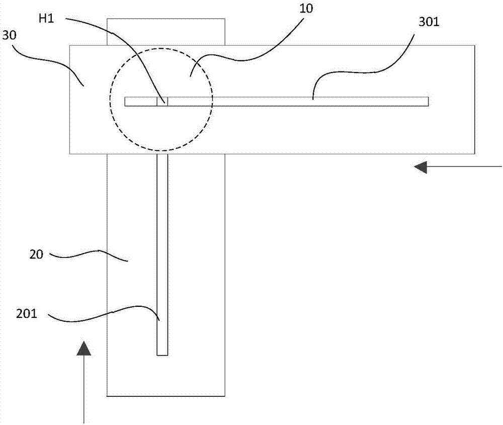
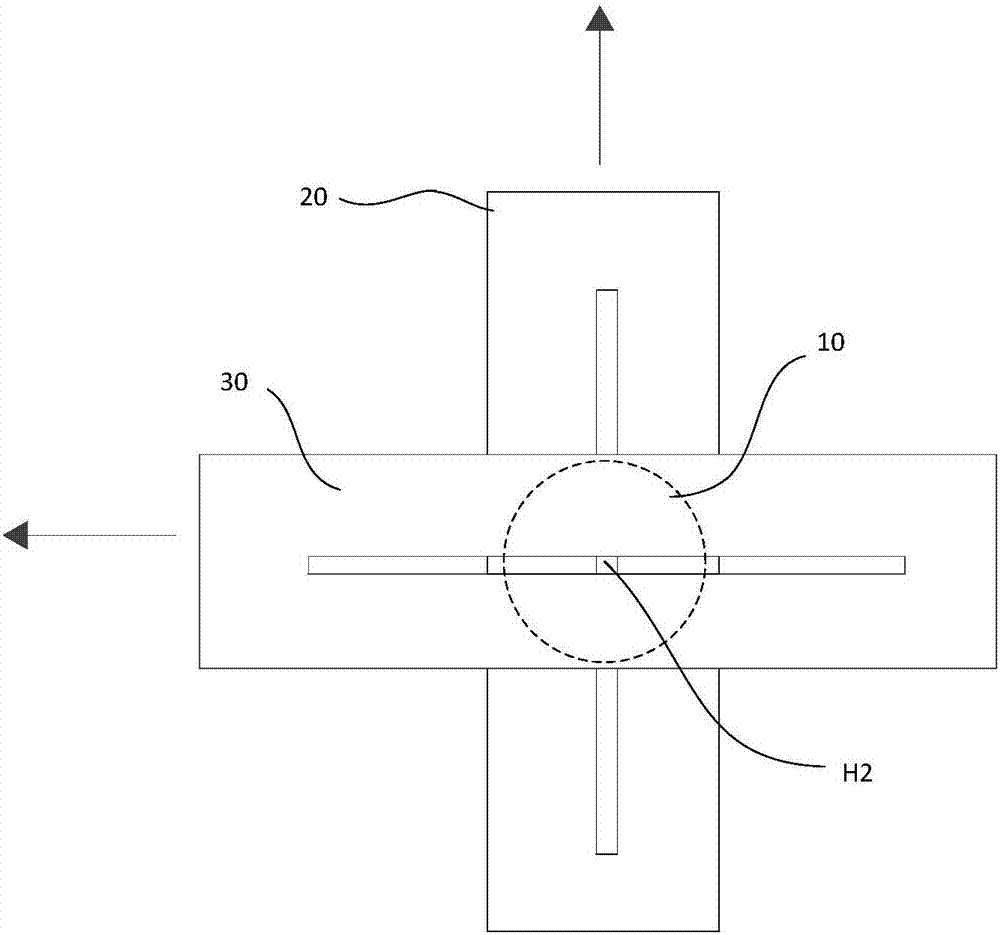
[0031] refer to figure 1 with figure 2 The evaporation source device of the present embodiment comprises a heating container 10 with an opening on the top surface and a first baffle plate 20 and a second baffle plate 30 covering the opening of the heating container 10. The heating container 10 is preferably a crucible, and the first baffle plate 20 and the second baffle plate 30 in the height direction of the heating container 10 (such as figure 1 The shown vertical direction) is stacked and the extension direction is crossed. The through holes on the first baffle plate 20 and the second baffle plate 30 are all strip-shaped holes extending along the length direction of the corresponding baffle plate, that is, the first A first strip-shaped hole 201 is opened on the baffle 20 , and a second strip-shaped hole 301 is opened on the second baffle 30 .

[0032] After being installed on the opening on the top surface of the heating container 10, the first baffle plate 20 and the s...

Embodiment 2

[0039] Such as Figure 5 As shown, different from Embodiment 1, the through holes on the first baffle plate 20 and the second baffle plate 30 of this embodiment are point-shaped through holes arranged at intervals in the length direction of the corresponding baffle plate, rather than one Overall strip hole.

[0040] During the process of moving the first baffle plate 20 and the second baffle plate 30, the dotted through holes of the first baffle plate 20 can cooperate with the corresponding dotted through holes of the second baffle plate 30 above it to form an evaporation channel H , when one of the point-shaped through holes of the first baffle plate 20 or the second baffle plate 30 is blocked, a new evaporation channel H can be formed by moving the baffle plate where the blocked point-shaped through-hole is located to replace the point-shaped through-hole.

[0041] It can be understood that, in other embodiments, the through holes on the first baffle plate 20 may be strip-s...

Embodiment 3

[0043] Such as Image 6 with 7 As shown, the difference from Embodiments 1 and 2 is that the first baffle plate 20 and the second baffle plate 30 of this embodiment are in the radial direction of the heating container 10 (ie figure 1 horizontal direction) adjacent to each other, the first baffle plate 20 and the second baffle plate 30 enclose the evaporation channel by splicing. Specifically, the first baffle 20 is provided with a plurality of first notches 200 arranged at intervals, and the second baffle 30 is provided with a plurality of second notches 300 arranged at intervals, and the second baffle 30 can Moving relative to the first baffle 20 , different first notches 200 cooperate with second notches 300 to form different evaporation channels.

[0044] Such as Image 6 , during the initial work, the first notch 200 on the edge of the first baffle 20 corresponds to the second notch 300 on the edge of the second baffle 30 one by one, and each first notch 200 is spliced ...


PUM


Abstract

The invention discloses an evaporation source device used for evaporation. The evaporation source device comprises a heating container with an opening in the top face, a first baffle and a second baffle, wherein the first baffle and the second baffle are arranged on the opening of the heating container in a covering manner. Through holes are formed in the first baffle and the second baffle correspondingly. The first baffle and the second baffle can relatively slide so that the through holes in the first baffle and the second baffle can cooperate at different cooperation positions with the number being at least two to form evaporation channels of the heating container. According to the evaporation source device, the first baffle and the second baffle are arranged at the position of the opening of the heating container, containing an organic electroluminescence material, in the covering manner, the first baffle and the second baffle can cooperate to form the different evaporation channels through movement of the first baffle and the second baffle, the evaporation channels can be replaced under the condition that a vacuum cavity is not opened, the problem that holes are blocked by the organic electroluminescence material in the evaporation process is well solved, and productivity and the product quality are improved.

Description

technical field [0001] The invention relates to the technical field of organic electroluminescent devices, in particular to an evaporation source device for evaporation. Background technique [0002] OLED (organic electroluminescent device) display is a new generation of display. By making organic thin film on OLED substrate, and the organic thin film is sandwiched between cathode and anode metal or conductive layer, voltage is applied to the two electrodes. Afterwards, the organic thin film will emit light. Compared with liquid crystal displays, OLED displays have many advantages such as self-illumination, fast response, wide viewing angle, and saturated colors. In recent years, the industrialization speed of OLEDs has advanced by leaps and bounds. [0003] At present, the mainstream method of preparing OLED display devices is vacuum thermal evaporation, that is, using a crucible to heat OLED organic materials in a vacuum chamber. The existing crucible for heating OLED ma...

Claims


Application Information

Patent Timeline
Patent Type & Authority Applications(China)
IPC IPC(8): C23C14/24
CPCC23C14/243C23C14/12C23C16/45563H10K71/164C23C14/545H10K71/00
Inventor 余威
Owner WUHAN CHINA STAR OPTOELECTRONICS SEMICON DISPLAY TECH CO LTD
Why Eureka
Try Eureka