Thread pulling device

It is a technology of pulling thread knife and clamping thread, which is applied in the field of thread threading device, which can solve the problems of easy thread removal, long distance, and large space occupation, and achieve the effect of not easy thread thread removal, stable seam start, and small space occupation

Active Publication Date: 2017-10-20
JACK SEWING MASCH CO LTD
View PDF6 Cites 5 Cited by
  • Summary
  • Abstract
  • Description
  • Claims
  • Application Information

AI Technical Summary

Problems solved by technology

In the above-mentioned bird’s nest removal device, the hook and the clamping plate are assembled together, which takes up a lot of space, and after the retracting hook returns to its position, the clamping plate is far away from the needle, the distance is long, and it is easy to take off the thread

Method used


Image

  • Thread pulling device
  • Thread pulling device
  • Thread pulling device

Examples


Embodiment 1

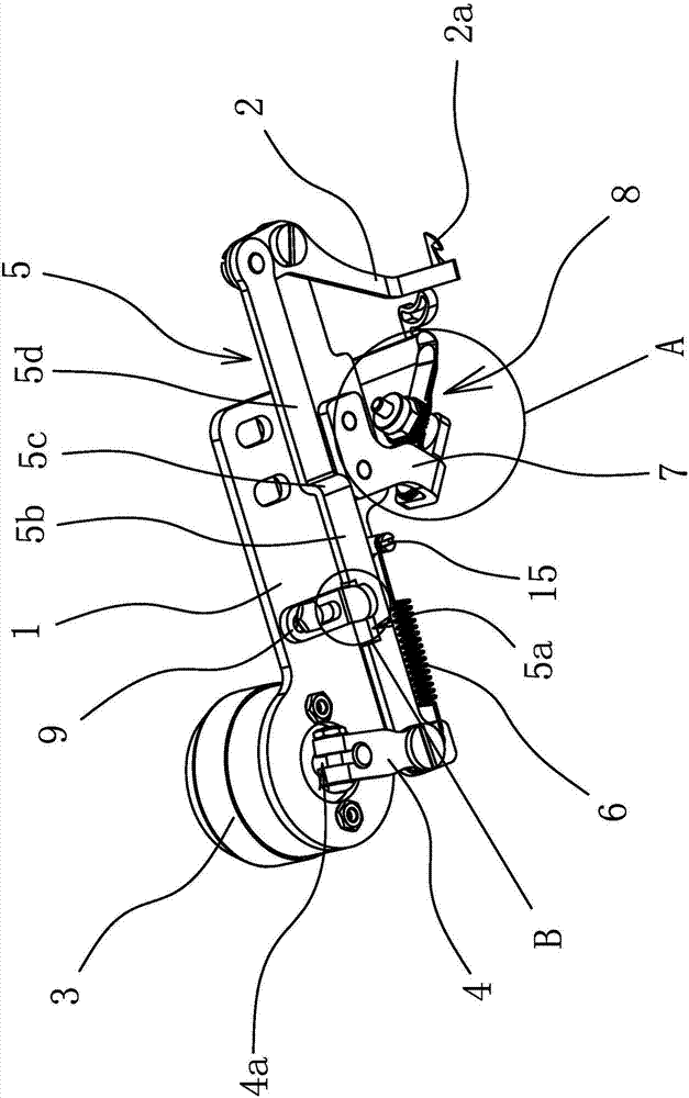
[0026] Such as figure 1 As shown, the wire pulling device is used to be installed on a sewing machine, and includes a mounting plate 1, a thread pulling knife 2 with a hook 2a at one end, a thread clamp assembly 8, a driving member and a mounting piece 7 detachably connected to the mounting plate 1 . The mounting plate 1 is in the shape of a long strip, the driving part is fixed on one end of the mounting plate 1, the middle part of the wire pulling knife 2 is hinged to the other end of the mounting plate 1 through a rotating shaft, and the driving part and the wire pulling knife 2 are respectively located on both sides of the mounting plate 1 , the mounting piece 7 and the wire wiper 2 are located on the same side of the mounting plate 1, and a drive crank 4 and a transmission connecting rod 5 are also arranged between the driver and the wire wiper 2 of the driving part.

[0027] Specifically, the driving part is a rotating electromagnet 3, and the rotating electromagnet 3 i...

Embodiment 2

[0033] The structure and features of this implementation are basically the same as in Embodiment 1, the difference is that: Figure 4 As shown, two eccentric shafts 16 are fixed on the mounting plate 1, and one end of the transmission connecting rod 5 hinged with the driving crank 4 has a downward bending baffle 5f, and the middle part of the transmission connecting rod 5 has a protruding limit The stop bar 5e, the baffle plate 5f and the stop bar are located between the two eccentric shafts 16, the baffle plate 5f can abut against one of the eccentric shafts 16 when the rotating electromagnet 3 drives the driving crank 4 to swing, and the stop bar 5e is on the drive crank. 4 can abut against another eccentric shaft 16 when returning to its position. The matching structure design of the two eccentric shafts 16 and the baffle plate 5f and the limit rod 5e respectively can limit the movement and the return stroke of the transmission connecting rod 5, thereby realizing the limit ...


PUM


Abstract

The invention provides a thread pulling device, and belongs to the technical field of machines, which can solve the problem that the conventional thread pulling devices are large in size, and often release threads. The thread pulling device includes an installation plate, a thread clamping assembly, a thread pulling cutter, and a drive member; the installation plate is long-bar-shaped; the drive member is fixed on one end of the installation plate, and the thread pulling cutter is hinged to the other end of the installation plate; one end of a transmission connection rod is hinged to the thread pulling cutter, and the other end of the transmission connection rod is hinged to a drive crank; the drive member is connected to the drive crank; a return spring is arranged between the drive crank and the installation plate; an installation sheet is detachably connected to the installation plate; the installation sheet is positioned under the transmission connection rod, and one end of the installation sheet extend under the installation plate; and the thread clamping assembly is fixed on the extension end, and is opposite to the thread pulling cutter. The thread pulling cutter and the thread clamping assembly are split, and the thread pulling device is reasonable in space layout and is small in size; after the thread pulling cutter returns, a pulling hook is positioned on the right side or under the right side of a needle; and the thread pulling device is stable in sewing, and can void thread jumping.

Description

technical field [0001] The invention belongs to the technical field of machinery and relates to a wire pulling device. Background technique [0002] When the sewing machine sews fabric, it is necessary to leave a certain length of thread at the needle eye of the machine needle at the beginning of sewing, so as to ensure that the thread will not come out of the needle eye when sewing starts, but a certain length of thread on the needle eye of the machine needle is at the beginning of sewing. When sewing, it will stay in the initial position of the sewing material, which will affect the appearance of the sewing material. The existing processing methods mainly include the following types: one is to use the thread puller to pull up the thread end when the last sewing is finished, and then rely on the sewing machine to sting the cloth to hook the thread to bring the thread end to the sewing material. Next, ensure the beauty of the front side of the sewing material. The other is...

Claims


Application Information

Patent Timeline
Patent Type & Authority Applications(China)
IPC IPC(8): D05B65/02D05B65/06
CPCD05B65/02D05B65/06
Inventor 李卫超田国兵洪建敏王志
Owner JACK SEWING MASCH CO LTD
Why Eureka
Try Eureka