
Double-movable-ring-beam continuous lifting mechanism and ascending and descending working method thereof

A lifting mechanism and working method technology, applied in infrastructure engineering, artificial islands, water conservancy projects, etc., can solve the problems of slow lifting speed and low efficiency of self-elevating platforms, and achieve fast lifting speed, reliable operation, easy use and maintenance convenient effect

Inactive Publication Date: 2017-10-20
708TH RES INST OF CSSC
View PDF3 Cites 0 Cited by
  • Summary
  • Abstract
  • Description
  • Claims
  • Application Information

AI Technical Summary

Problems solved by technology

[0003] The existing hydraulic bolt lifting mechanism is set with dynamic and static ring beams. The static ring beam is used for supporting and turning, and the moving ring beam is used for lifting. The lifting speed of the type platform is slow and the efficiency is low

Method used


Image

  • Double-movable-ring-beam continuous lifting mechanism and ascending and descending working method thereof
  • Double-movable-ring-beam continuous lifting mechanism and ascending and descending working method thereof

Examples


Embodiment approach

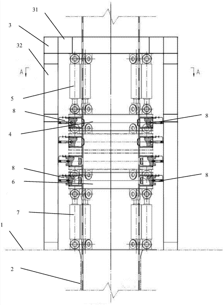
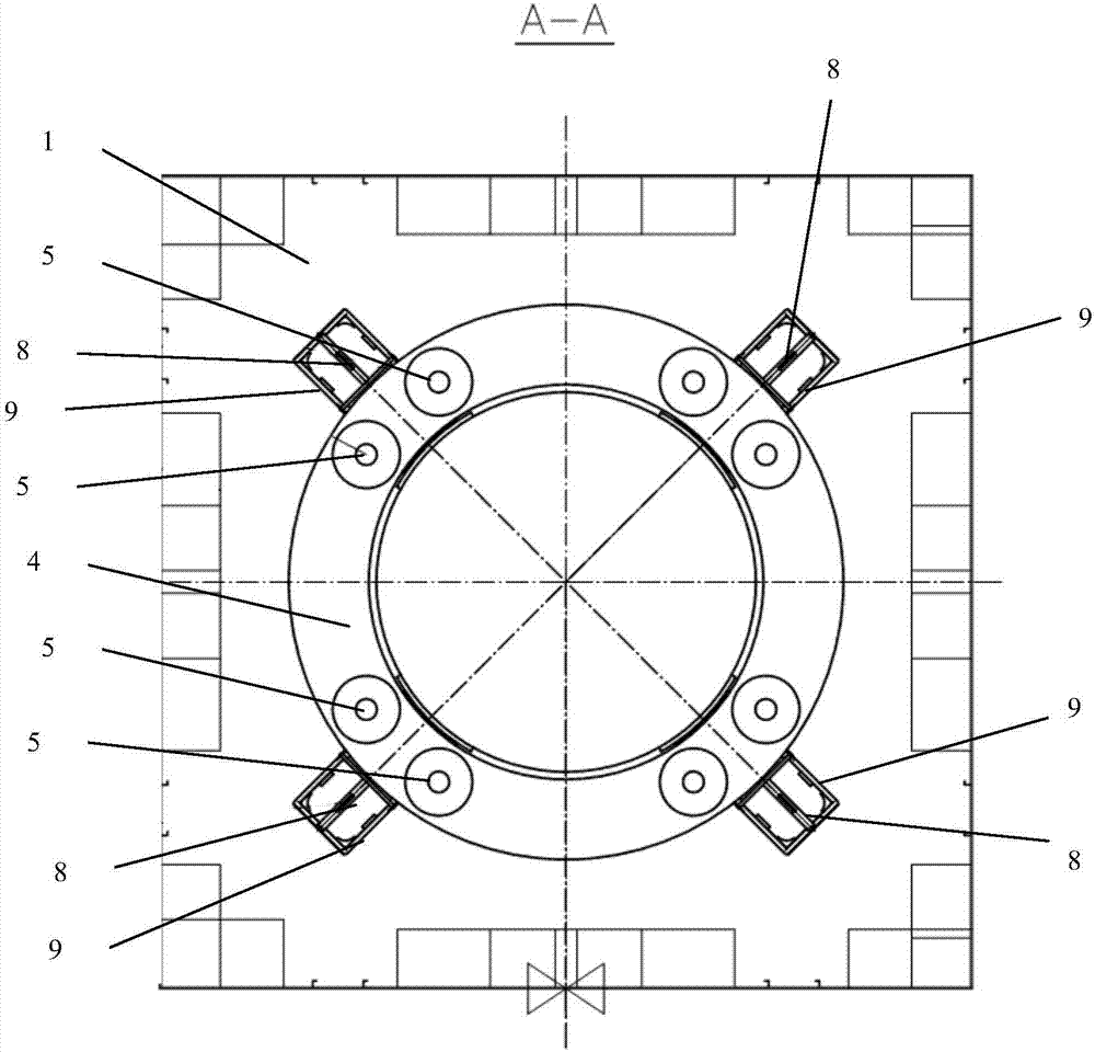
[0043] In further embodiments of the present invention, please continue to refer to figure 1 , figure 2 As shown, both the upper moving ring beam 4 and the lower moving ring beam 6 are box-shaped structures with circular cross-sections or box-shaped structures with polygonal cross-sections.

[0044] In a further embodiment of the present invention, the number of the upper lifting cylinder 5 and the lower lifting cylinder 7 is four, eight or twelve.

[0045] In further embodiments of the present invention, please continue to refer to figure 2 As shown, a bolt bracket 9 is included, and the bolt bracket 9 is a rectangular frame, and the bolt bracket 9 is fixedly connected with the upper moving ring beam 4 or the lower moving ring beam 6 , and a bolt 8 is arranged inside the bolt bracket 9 .

[0046] In a further embodiment of the present invention, several bolt brackets 9 are included, and several bolt brackets 9 form a circular array around the upper moving ring beam 4 or t...


PUM


Abstract

The invention discloses a double-movable-ring-beam continuous lifting mechanism and an ascending and descending working method thereof. The double-movable-ring-beam continuous lifting mechanism comprises a pile fixing chamber, an upper movable ring beam, an upper lifting oil cylinder, a lower movable ring beam and a lower lifting oil cylinder, wherein the pile fixing chamber is positioned at joint parts of a platform and pile legs; the lower end of the pile fixing chamber is fixedly connected with the platform; the upper movable ring beam is of an annular structure and is arranged on the outer sides of a plurality of pile legs in a sleeving manner; the cylinder block of the upper lifting oil cylinder is hinged to the inner wall of the upper end of the pile fixing chamber; a piston rod of the upper lifting oil cylinder is hinged to the upper surface of the upper movable ring beam; the lower movable ring beam is of an annular structure, is arranged on the outer sides of a plurality of pile legs in a sleeving manner and is positioned below the upper movable ring beam; the cylinder block of the lower lifting oil cylinder is hinged to the upper surface of the platform; and a piston rod of the lower lifting oil cylinder is hinged to the lower surface of the lower movable ring beam. The double-movable-ring-beam continuous lifting mechanism adopts innovative double-movable-ring-beam arrangement, the upper movable ring beam and the lower movable ring beam are of movable structures and are cooperated with simultaneous stretching and retraction action of the lifting oil cylinders and insertion and pull-out dynamic load of bolts to realize continuous ascend and descend of the platform and the pile legs.

Description

technical field [0001] The invention relates to the technical field of lifting mechanisms, in particular to a double-moving ring beam continuous lifting mechanism. Background technique [0002] The jack-up platform is mainly composed of three parts: the platform main body (hull), pile legs and lifting mechanism. The lifting mechanism is installed at the junction of the main body of the platform and the legs. When working, rely on the lifting mechanism to lower the pile legs and insert them into a certain depth below the mud surface of the seabed. After compaction, the main body of the platform is raised to a certain height above the water surface without being hit by waves, and then the operation can be carried out. When the platform is working, the lifting mechanism transfers the vertical load caused by the platform's own weight and operation to the pile legs; bit or tow phase. [0003] The existing hydraulic bolt lifting mechanism is set with dynamic and static ring bea...

Claims


Application Information

Patent Timeline
IPC IPC(8): E02B17/04E02B17/08
CPCE02B17/04E02B17/0809
Inventor 费龙张志泉丁勇吴雪峰
Owner 708TH RES INST OF CSSC
Learn More