Magnetic element

A technology of magnetic components and isolation components, applied in electrical components, magnetic cores/yokes, inductors with magnetic cores, etc., can solve the problems of increased energy consumption, limited efficiency improvement, high magnetic flux leakage, etc., to reduce magnetic flux leakage and magnetic loss, improving the utilization rate of windings, and increasing the number of windings

Inactive Publication Date: 2017-10-20
SPI ELECTRONICS
View PDF6 Cites 2 Cited by
  • Summary
  • Abstract
  • Description
  • Claims
  • Application Information

AI Technical Summary

Problems solved by technology

[0002] Figure 1A , 1B Indicates a conventional inductive element, conventional magnetic elements such as transformers, inductive elements, etc. will use a single air gap 14 formed between the central column 111 of the first magnetic core 11 and the central column 121 of the second magnetic core 12 to avoid magnetic saturation , however, if the distance between such a single air gap 14 is too large, it will cause higher flux leakage, resulting in increased energy consumption
And conventional magnetic components with an air gap need to use the winding frame 10 to fix the winding group 13 between the first magnetic core 11 and the second magnetic core 12, which will reduce the number of winding groups that can be accommodated, and reduce the Winding utilization rate and working efficiency of magnetic components
There are magnetic components on the market that set multiple air gaps in the center column to reduce and disperse the leakage loss and reduce the diffusion flux, but the distribution and number of air gaps in the center column of the magnetic core have their limits, and when the number of air gaps increases, the air gap The distance between the air gaps will become smaller, and when the distance between the air gaps is less than a certain length, the diffusion flux cannot be continuously and effectively reduced, so the efficiency improvement is limited

Method used


Image

  • Magnetic element
  • Magnetic element
  • Magnetic element

Examples


Embodiment Construction

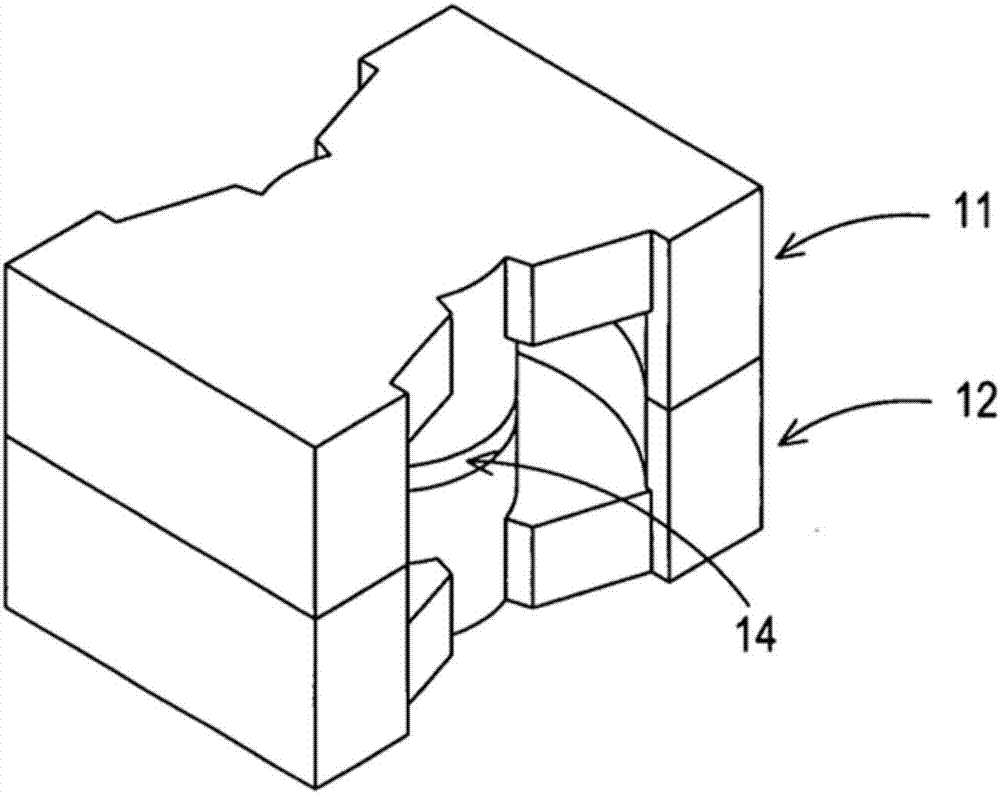
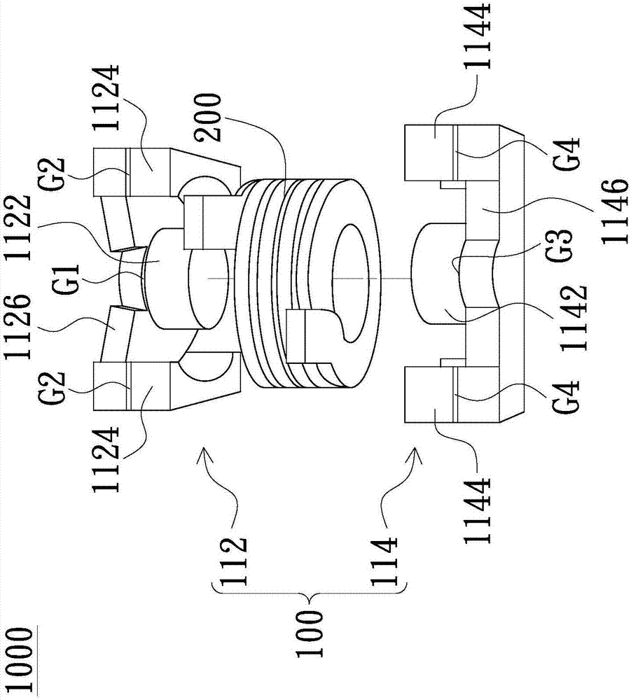
[0076] see Figure 2A , 2B and 3A, which represent an embodiment of the magnetic element of the present invention. The magnetic element 1000 of the present invention includes a magnetic core 100 and a winding set 200 . Such as Figure 3A As shown, the magnetic core 100 has a central column 110, two side columns 120 and a winding space 130, as Figure 2B As shown, the winding group 200 is arranged in the winding space 130 and wound around the central column 110, wherein the central column 110 forms two central column air gaps G1, G3 and each side column 120 forms two side columns respectively The air gaps G2 and G4, and the magnetic core piece 100 are made of magnetically permeable material.

[0077] Such as Figure 2A As shown, in this embodiment, the magnetic core member 100 includes a first magnetic core 112 and a second magnetic core 114 that are butted with each other, the first magnetic core 112 has a first central column 1122 and two first side columns 1124, the sec...


PUM


Abstract

A magnetic element of the present invention includes a magnetic core member and a winding. The magnetic core member includes a central post, at least one lateral post and a winding space, and the winding is disposed in the winding space and around the central post. The central post includes a plurality of central air gaps, and the at least one lateral post includes a plurality of lateral air gaps. Since the magnetic element of the present invention includes several air gaps formed in the central post and the lateral posts and distributed uniformly on the entire magnetic path, such a structure prevents magnetic saturation and controls the magnetic leakage loss in a desired range. In addition, since the winding of the magnetic element of the present invention is directly disposed on the central post without a winding frame, the number of windings is thus increased so as to improve utilization ratio of the winding and working efficiency of the magnetic element.

Description

technical field [0001] The present invention relates to a magnetic element, in particular to a magnetic element forming a plurality of air gaps on a magnetic circuit. Background technique [0002] Figure 1A , 1B Indicates a conventional inductive element, conventional magnetic elements such as transformers, inductive elements, etc. will use a single air gap 14 formed between the central column 111 of the first magnetic core 11 and the central column 121 of the second magnetic core 12 to avoid magnetic saturation , however, if the distance between the single air gap 14 is too large, it will cause higher flux leakage, resulting in increased energy consumption. And conventional magnetic components with an air gap need to use the winding frame 10 to fix the winding group 13 between the first magnetic core 11 and the second magnetic core 12, which will reduce the number of winding groups that can be accommodated, and reduce the Winding utilization rate and working efficiency o...

Claims


Application Information

Patent Timeline
Patent Type & Authority Applications(China)
IPC IPC(8): H01F17/04H01F27/24H01F3/14H01F27/28
CPCH01F3/14H01F17/045H01F27/24H01F27/263H01F27/2847H01F41/0246
Inventor 林国藩涂富凯
Owner SPI ELECTRONICS
Why Eureka
Try Eureka