Automatic cleaning mop mopping machine

An automatic cleaning and floor mopping technology, which is applied to manual floor scrubbing machines, carpet cleaning, floor cleaning, etc., can solve problems such as troublesome, inability to continuously mop the floor, and untimely removal and cleaning, so as to improve the cleaning effect and save energy. The effect of water is obvious and beneficial to environmental protection

Inactive Publication Date: 2017-10-24
SUINING CHANGFENG MECHANICAL TECH
View PDF0 Cites 11 Cited by
  • Summary
  • Abstract
  • Description
  • Claims
  • Application Information

AI Technical Summary

Problems solved by technology

Although a lot of water was flushed, the flat plate blocked the water on it, and many parts of the mop couldn’t be washed at all, and it couldn’t be washed clean.
The second is that the strip-shaped mop is relatively long, and there is no special dehydration device. After cleaning the strip-shaped mop, the cleaners carry it to mop the floor, causing running water while walking, and people who come and go walk on the ground.
The third is that most of the handkerchiefs are rinsed in the toilet, and it is troublesome, laborious and time-consuming to wash the handkerchiefs once. The cleaners often finish mopping a un

Method used


Image

  • Automatic cleaning mop mopping machine
  • Automatic cleaning mop mopping machine
  • Automatic cleaning mop mopping machine

Examples


Embodiment Construction

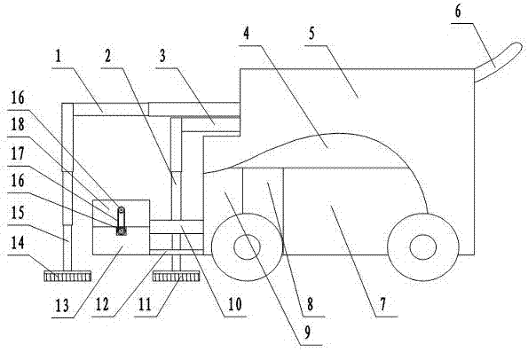
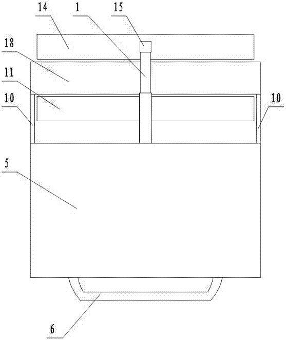
[0021] figure 1 In the middle, it is the overall structure diagram of the split-type mopping model of the automatic cleaning mopping machine. The split-type mopping model of the automatic cleaning mopping machine is hereinafter referred to as the split mopping machine. figure 1 In, is the side view of the split mopping machine. figure 2 in, yes figure 1 top view. combine figure 1 , figure 2 Narrate together. A front arm frame 1 and a rear arm frame 3 are installed on the front top of the vehicle body 5 . The front arm frame 1 is above the rear arm frame 3 . figure 2 Among them, the front arm frame 1 blocks the rear arm frame 3 and cannot be seen. The front end of the forearm is vertically connected with the upper end of the premise bar 15 . The front end of the rear arm frame 3 is vertically connected with the upper end of the rear lifting rod 2 . Premise bar 15 lower ends are connected in the middle of the flat plate above front handkerchief 14. The lower end of...


PUM


Abstract

The invention relates to an automatic cleaning mop mopping machine. The machine comprises lift rods, a mop, arm racks, a cleaning pond, a machine body, a water supply and drainage part and a control system. The mopping machine has a mop front type and a mop split type. A front mop and a back mop are arranged in front of the machine body. The cleaning pond is connected to the front of the machine body. Upper flat plates of the front mop and the back mop are connected to the lower ends of the front lift rod and the back lift rod. The upper ends of the front lift rod and the back lift rod are connected with the front ends of the front arm rack and the back arm rack. Two mops clean and mop the floor automatically by turns. Heavy, secondary and light slop tanks and a clear water tank are arranged on the machine body. When the mops are cleaned, the lift rods are matched with the arm racks, the mops are lifted and moved to the center right opposite to the cleaning pond, and the mops are placed in the cleaning pond. Stir-wash and dehydration are conducted by using the water in the secondary slop tank, the light slop tank, and the clear water tank in sequence. The waste water of the first time and the second time is discharged into the slop tank, and the water which is cleaned by clear water for last two times is discharged into the secondary slop tank and the light slop tank. According to the automatic cleaning mop mopping machine, a large amount of cleaning water is saved, so that the mopped floor is cleaner, and the work efficiency is improved. The situation that machine-loading long strip shaped mops cannot be cleaned automatically is avoided.

Description

technical field [0001] The invention belongs to the field of environmental protection machinery, in particular to an automatic cleaning mopping machine. Background technique [0002] Now most of the environmental cleaning workers in residential areas, shopping malls, entertainment and leisure places, restaurants, hotels, and office areas use long strips of handkerchiefs to mop the floor. The strip-shaped mopping handkerchief is longer and the mopping area is wider at one time. But the cleaning of strip-shaped mop has always been a very troublesome thing. One is that there is no such long elongated water basin and pond as an elongated mopping handkerchief. Most of them are showered with water and rinsed with tap water. Although a lot of water was flushed, the flat plate blocked the water, and many parts of the mop couldn't be washed at all, and it couldn't be washed clean. The second is that the strip-shaped mop is relatively long, and there is no special dehydration devi...

Claims


Application Information

Patent Timeline
IPC IPC(8): A47L11/28A47L11/40
CPCA47L11/28A47L11/40A47L11/4016A47L11/4055A47L11/4072
Inventor 邹家福屈胜英
Owner SUINING CHANGFENG MECHANICAL TECH
Why Eureka
Try Eureka