Drill pin grinding positioning method

A positioning method and technology of drill pins, which are applied in the direction of drilling tool accessories, grinding workpiece supports, grinding drive devices, etc., can solve the problems that the clamping force of the clamping drill pins cannot be kept consistent, and the grinding error of the drill pins is increased. To achieve the effect of improving efficiency, increasing the degree of automation, and simplifying the mechanism structure

Inactive Publication Date: 2017-10-24
CHANGZHOU DOMOCO INTELLIGENT EQUIP CO LTD
View PDF0 Cites 2 Cited by
  • Summary
  • Abstract
  • Description
  • Claims
  • Application Information

AI Technical Summary

Problems solved by technology

[0002] In the existing grinding and positioning method for drill needles, the clamping degree of the drill needle is generally determined according to the displacement of the clamping block when the clamping device is used to clamp the drill needle. Due to the large error in this control method, each time The clamping force of the clamping drill bit cannot be kept consistent, thus increasing the grinding error of the drill bit during the grinding process

Method used


Image

  • Drill pin grinding positioning method
  • Drill pin grinding positioning method
  • Drill pin grinding positioning method

Examples


Embodiment Construction

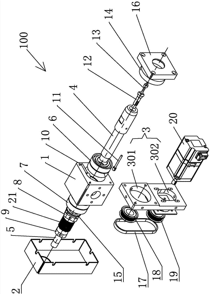
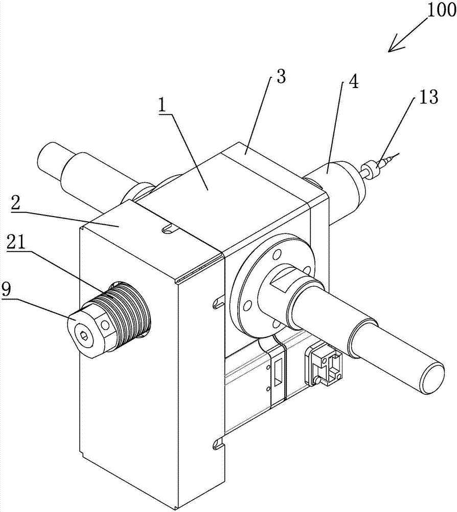
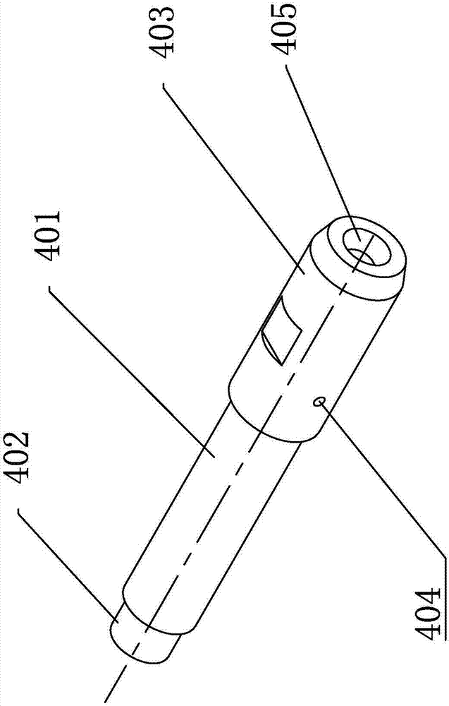
[0030] like Figure 1-10 As shown, the drill bit grinding and positioning device in the present invention includes: a housing 1, a rear end cover 2, a front end cover 3, an outer shaft 4, an inner shaft 5, a first bearing 6, a second bearing 7, a first locking Block 8, second locking block 9, pin 10, limit rod 11, collet 12, drill needle 13, first spacer 14, second spacer 15, fixed plate 16, conveyor belt 17, first pulley 18 , second pulley 19, motor 20, disc spring 21, rotating shaft 22, support frame 23, servo motor one 24, cylinder 25, slide plate 26, base 27, servo motor two 28, clamping part one 29, clamping Part two 30, servo motor three 31, first clamping block 32, second clamping block 33, support seat 34.

[0031] The drill clamping device 100 includes a housing 1, the housing 1 is provided with a through hole, and the outer shaft 4 rotates with the through hole through the first bearing 6 and the second bearing 7 provided in the through hole. The outer shaft 4 incl...


PUM


Abstract

The invention relates to a grinding and positioning method for drill pins, which includes: a servo motor controls a pair of clamping blocks to move relative to each other to clamp the drill pins, and a controller electrically connected to the servo motors detects the rotation angle of the servo motors to obtain the relative movement of the clamping blocks. At the same time, the controller detects the torque value output by the servo motor and calculates the clamping force of the pair of clamping blocks. When the relative displacement of the clamping blocks reaches the set value and the clamping force reaches the set value, the control The controller judges that the drill pin is clamped; the controller detects the rotation angle of the servo motor to obtain the relative displacement of the clamping block, and the controller detects the torque value output by the servo motor to obtain the clamping force, and uses the relative displacement and the clamping force to judge at the same time The clamping degree of the clamping block has higher control precision.

Description

technical field [0001] The invention relates to a grinding and positioning method for a drill, which is used for grinding and positioning the drill. Background technique [0002] In the existing grinding and positioning method for drill needles, the clamping degree of the drill needle is generally determined according to the displacement of the clamping block when the clamping device is used to clamp the drill needle. Due to the large error in this control method, each time The clamping force for clamping the drill pin cannot be kept consistent, thereby increasing the grinding error of the drill pin during the grinding process. Contents of the invention [0003] The technical problem to be solved by the present invention is to provide a grinding and positioning method for a drill, which can more precisely control the clamping degree of the drill. [0004] In order to solve the above-mentioned technical problems, the present invention provides a drill bit grinding and posi...

Claims


Application Information

Patent Timeline
Patent Type & Authority Applications(China)
IPC IPC(8): B24B3/24B24B41/06B24B49/00B24B47/00
CPCB24B3/24B24B3/247B24B47/00B24B49/00
Inventor 袁启营
Owner CHANGZHOU DOMOCO INTELLIGENT EQUIP CO LTD
Why Eureka
Try Eureka