Negative pressure precision injection molding method for mobile phone plastic parts

A technology of injection molding and plastic parts, applied in coating and other directions, can solve the problems that affect the performance and surface quality of plastic parts of mobile phones, the products are easy to stick to the fixed template, and the size of injection molding cannot be processed, so as to achieve good radiation resistance and cost performance. High, prevent deformation and damage effect

Inactive Publication Date: 2017-10-24
东莞市中萃模具塑胶科技有限公司
View PDF2 Cites 8 Cited by
  • Summary
  • Abstract
  • Description
  • Claims
  • Application Information

AI Technical Summary

Problems solved by technology

A lot of plastic parts are needed to make a mobile phone. The existing injection molding molds for mobile phone plastic parts are all injected and demoulded under normal pressure. During injection molding, due to the presence of air in the cavity, the plastic raw materials cannot be filled quickly. Cavity, the injection speed is slow, and the oxygen in the cavity will react with the plastic raw material, causing the plastic raw material to burn, affecting the performance and surface quality of the plastic parts of the mobile phone, making it impossible for injection molding to process more precise, small-sized and thin-walled products; When demolding, because the product is easy to stick to the fixed template, it is not easy to demould, and the ejector pin is used to directly eject the product, which may easily lead to product deformation and damage

Method used


Image

  • Negative pressure precision injection molding method for mobile phone plastic parts
  • Negative pressure precision injection molding method for mobile phone plastic parts
  • Negative pressure precision injection molding method for mobile phone plastic parts

Examples


Embodiment Construction

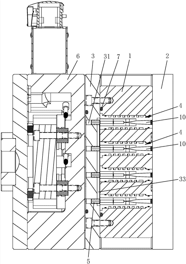
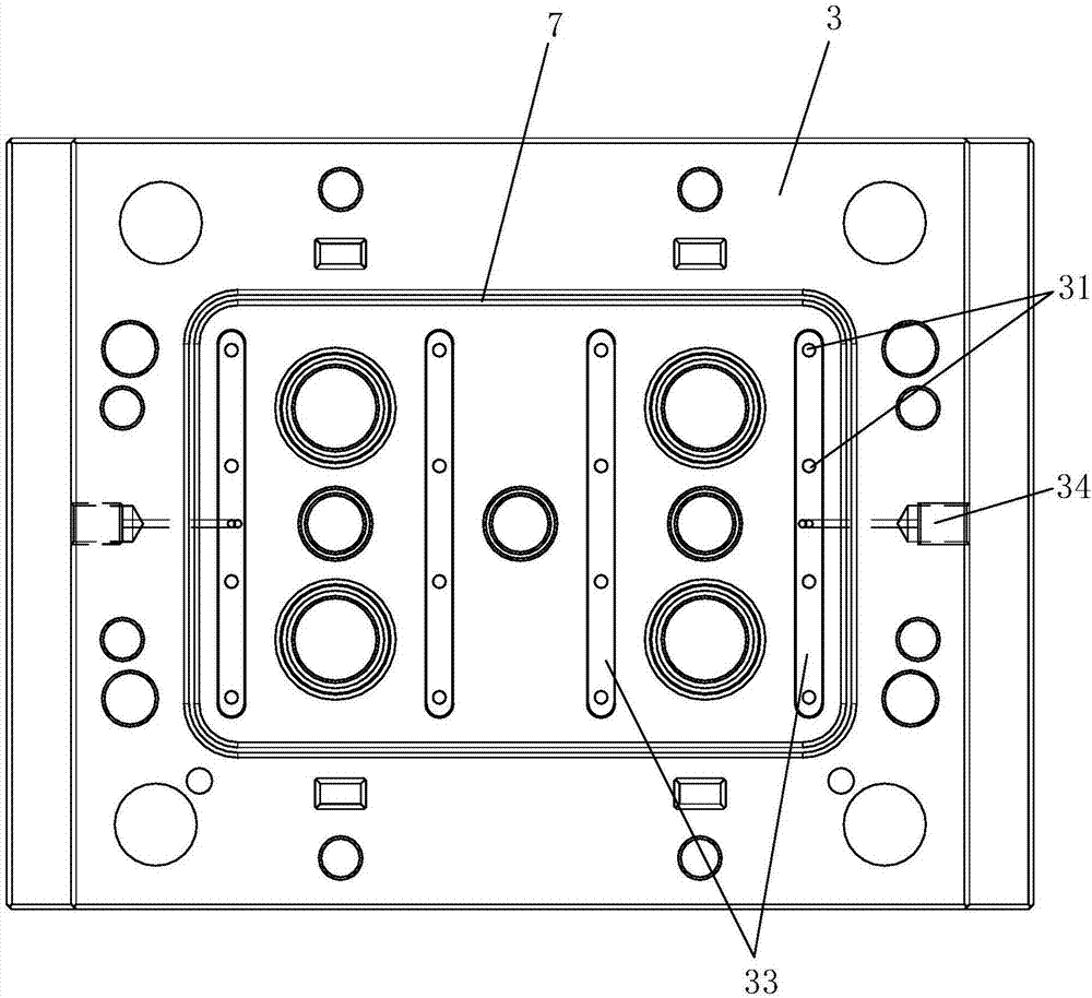
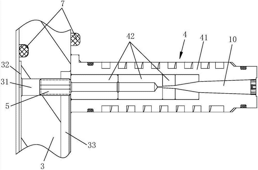
[0021] The present invention will be further described below in conjunction with accompanying drawing and preferred embodiment, see Figure 1~3 As shown, in the negative pressure precision injection molding method for mobile phone plastic parts of the present invention, the molding mold adopted includes a fixed template 1, a movable template 2 matched with the fixed template 1, the movable template 2 is arranged on the rear end surface of the fixed template 1, and the fixed template 1 is provided with a plurality of cavity 10 inside, and a cover plate 3 is provided on the front surface of the fixed template 1, and a plurality of inlet and outlet air holes 31 respectively corresponding to the plurality of mold cavities 10 are opened on the cover plate 3, and each inlet and outlet air hole 31 is respectively It communicates with the corresponding mold cavity 10, and the multiple inlet and outlet air holes 31 communicate with each other through the ventilation groove 32, and the v...


PUM

PropertyMeasurementUnit
diameteraaaaaaaaaa

Abstract

The invention relates to the technical field of plastic injection molding, in particular to a negative pressure precision injection molding method for mobile phone plastic parts. The method includes the steps that air in a forming mold cavity is sucked out to form negative pressure through an air compression system at first, and then a plastic raw material in the molten state is injected to the cavity to form a product; and in the demolding process, gas is blown into the forming mold cavity through the air compression system, and thus the product can be separated from a fixing mold plate. By means of the negative pressure precision injection molding method for the mobile phone plastic parts, injection molding can be conducted on the cavity in the negative pressure state, the cavity can be filled with the injection molding plastic raw material quickly, and injection molding efficiency is high; moreover, the phenomenon that oxygen in the cavity is reacted with the plastic raw material to burn the plastic raw material is avoided, the performance, surface quality and precision of the mobile phone plastic parts are improved, and injection molding of small-size precision thin-walled products can be achieved; and the products can be blown out in a positive pressure gas blowing mode, the products can be prevented from being attached to the fixing mold plate, product deformation and damage are also prevented, and demolding is easy.

Description

Technical field: [0001] The invention relates to the technical field of plastic injection molding, in particular to a negative pressure precision injection molding method for plastic parts of mobile phones. Background technique: [0002] Injection molding of plastic products is a processing method used in the mass production of some parts with complex shapes. Specifically, it refers to injecting heated and melted materials into the mold cavity under high pressure, and after cooling and solidifying, molded products are obtained. A lot of plastic parts are needed to make a mobile phone. The existing injection molding molds for mobile phone plastic parts are all injected and demoulded under normal pressure. During injection molding, due to the presence of air in the cavity, the plastic raw materials cannot be filled quickly. Cavity, the injection speed is slow, and the oxygen in the cavity will react with the plastic raw material, causing the plastic raw material to burn, affec...

Claims


Application Information

Patent Timeline
Patent Type & Authority Applications(China)
IPC IPC(8): B29C45/00B29C45/26B29C45/32B29C45/34B29C45/43B29C45/17
CPCB29C45/0005B29C45/0025B29C45/1701B29C45/2602B29C45/32B29C45/34B29C45/43B29C2045/4063B29K2201/08
Inventor 钟灿秋
Owner 东莞市中萃模具塑胶科技有限公司
Why Eureka
Try Eureka