
A kind of anti-flooding structure of underground garage

An underground garage and anti-flooding technology, which is applied to drainage structures, water supply devices, waterway systems, etc., can solve problems such as not being well solved, difficult to ensure sealing, and flowing into underground garages, so as to prevent water seepage and avoid working life. , Improve the sealing effect

Active Publication Date: 2020-07-03
聊城泽润装饰工程有限公司
View PDF6 Cites 0 Cited by
  • Summary
  • Abstract
  • Description
  • Claims
  • Application Information

AI Technical Summary

Problems solved by technology

Generally, underground garages are equipped with drainage ditches at the upper and lower ends of the ramp, and there are drainage pumps in the garage. However, when the rainfall reaches a certain level and exceeds the designed drainage capacity, the accumulated water on the surface will flow into the underground garage along the ramp, causing the garage to be flooded. If certain measures are taken to prevent surface water from flowing into the garage along the ramp, the problem of garage flooding can be solved smoothly; the water blocking plate of the existing underground garage water blocking structure is difficult to ensure sealing because it is set on the ground Moreover, after the water blocking plate is rotated and raised, the problem of water leakage in the gap between it and the water retaining wall has not been well solved.

Method used


Image

  • A kind of anti-flooding structure of underground garage
  • A kind of anti-flooding structure of underground garage

Examples


Embodiment Construction

[0016] The following will clearly and completely describe the technical solutions in the embodiments of the present invention with reference to the accompanying drawings in the embodiments of the present invention. Obviously, the described embodiments are only some, not all, embodiments of the present invention. Based on the embodiments of the present invention, all other embodiments obtained by persons of ordinary skill in the art without making creative efforts belong to the protection scope of the present invention.

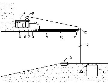
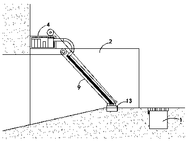
[0017] refer to Figure 1-2 , an underground garage anti-flooding structure, including a drainage ditch 1 arranged on the front side of the garage entrance and water retaining walls 2 arranged on both sides of the garage entrance, the drainage ditch 1 is provided with a rainwater grate, and the side wall of the drainage ditch 1 A liquid level sensor 14 is provided. It should be noted that the side wall of the drainage ditch 1 is provided with a groove, and the...


PUM


Abstract

The invention discloses an underground garage waterflooding preventing structure. The structure comprises a drainage ditch and water-retaining walls, wherein the drainage ditch is arranged on the front side of a garage entrance, and the water-retaining walls are arranged on the two sides of the garage entrance. A liquid level sensor is arranged on the side wall of the drainage ditch, a transverse plate is connected between the upper ends of the two water-retaining walls, a control box is arranged at the upper end of the transverse plate, and a controller is arranged inside the control box; an accumulator and an air pump are further arranged inside the liquid level sensor, an air inlet end of the air pump communicates with the outer portion of the control box, a winch is installed on the upper side of the control box, and a water-retaining plate is rotatably connected with the front end of the transverse plate; a rope of the winch is connected with the top surface of the front end of the water-retaining plate, air bags are connected with the left side and the right side of the water-retaining plate correspondingly, and the air bags are connected with an air outlet end of the air pump; and a sealing gasket is connected with the front end of the water-retaining plate, an electromagnet is installed in the sealing gasket, and an iron plate is embedded into the bottom surface of the garage entrance. According to the underground garage waterflooding preventing structure, good sealing can be automatically conducted on the garage entrance, and the waterflooding preventing structure is high in working efficiency and long in service life.

Description

technical field [0001] The invention relates to an electric water retaining device, in particular to an anti-flooding structure of an underground garage. Background technique [0002] At present, there are a large number of underground garages in the city, and these garages often become the hardest hit areas when they are hit by heavy rain. Generally, underground garages are equipped with drainage ditches at the upper and lower ends of the ramp, and there are drainage pumps in the garage. However, when the rainfall reaches a certain level and exceeds the designed drainage capacity, the accumulated water on the surface will flow into the underground garage along the ramp, causing the garage to be flooded. If certain measures are taken to prevent surface water from flowing into the garage along the ramp, the problem of garage flooding can be solved smoothly; the water blocking plate of the existing underground garage water blocking structure is difficult to ensure sealing beca...

Claims


Application Information

Patent Timeline
Patent Type & Authority Patents(China)
IPC IPC(8): E04H6/42E03F5/00E05C19/16E05F15/53E05F15/72E06B7/22
CPCE03F5/00E04H6/42E05C19/166E05F15/53E05F15/72E06B7/22
Inventor 张健
Owner 聊城泽润装饰工程有限公司
Learn More