Split type impeller

A split-type impeller technology, which is applied to non-variable pumps, liquid fuel engines, and parts of pumping devices for elastic fluids. Problems such as the inability to change the blade angle can achieve the effect of simplifying the design and manufacturing process, saving the cost of use, and simplifying the structure

Active Publication Date: 2017-10-24
HUNAN LIANCHENG TRACK EQUIP CO LTD
View PDF6 Cites 2 Cited by
  • Summary
  • Abstract
  • Description
  • Claims
  • Application Information

AI Technical Summary

Problems solved by technology

[0002] Fan impellers are widely used in hydraulic cooling, heat exchange systems, ventilation systems and other fields. Most of the existing fan impellers are integral structures, and fan impellers generally have a large number of blades. It is difficult to make molds for integral impellers, and the cost also increases. In addition, in the existing impellers, the installation angle of the blades is mostly non-adjustable, and it is impossible to change the blade angle according to the actual application needs (such as air volume and wind pressure). Therefore, it needs to be redesigned and manufactured according to different application needs. impeller, further increasing the cost

Method used


Image

  • Split type impeller
  • Split type impeller
  • Split type impeller

Examples


Embodiment Construction

[0021] The embodiments of the present invention will be described in detail below with reference to the accompanying drawings, but the present invention can be implemented in various ways defined and covered by the claims.

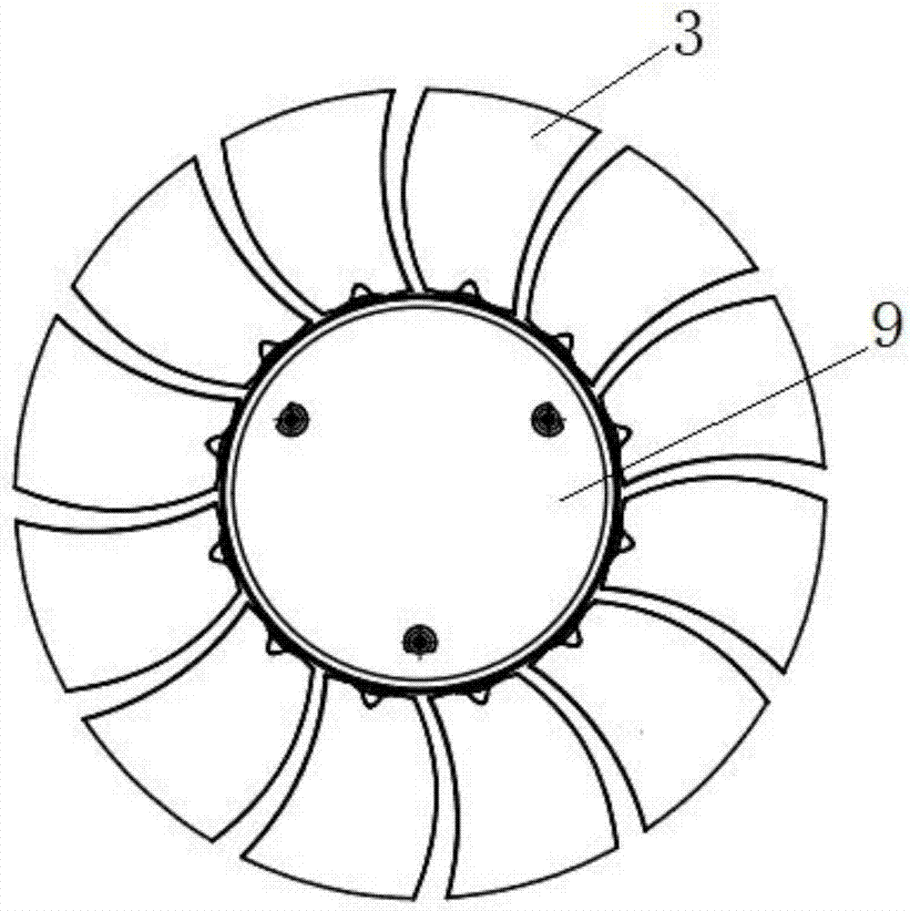
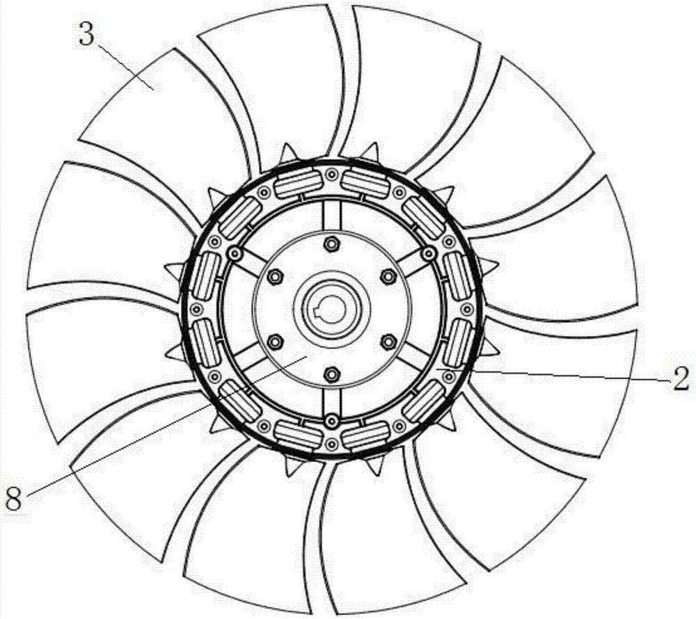
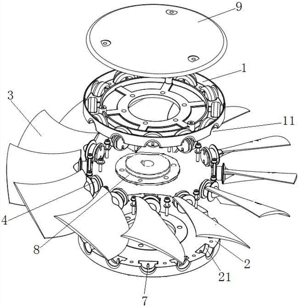
[0022] see Figure 1 ~ Figure 3 The split impeller comprises hub one 1, hub two 2 and several blades 3 respectively connected and arranged between the edge of hub one and hub two, and each blade is symmetrically distributed on the radial periphery of hub one and hub two, The root of the blade is provided with a mounting column 4 for connecting the hub 1 and the hub 2, and the edges of the hub 1 and the hub 2 are respectively provided with a positioning groove 11 and a positioning groove 2 21, and the positioning groove 1 and the positioning groove 2 are docked (along the hub 1 and the hub 2). The axial direction of the second butt joint) can be partially or completely fitted and matched with the outer cylindrical surface of the installation column, so that...


PUM


Abstract

The invention provides a split type impeller. The root of a blade (3) is provided with an installation column (4) used for connecting a first hub (1) with a second hub (2), a first convex part (41) is arranged on an exterior cylindrical surface of the installation column in a protruding mode, the positions, corresponding to the first convex part, of a first fixing groove (11) and a second fixing groove (12) are set into groove face structures matched with the first convex part, an inner cavity of the installation column is detachably and internally provided with an adjusting block (5), and a guide groove (6) and a second convex part (7) are arranged between the adjusting block and the first fixing groove or the second fixing groove and matched in a sliding mode in the direction perpendicular to the axis of the installation column. The split type impeller is simple in structure, the design and production process of a mold is simplified, the installation angle of the blade can be changed by replacing the second fixing groove and arranging adjusting blocks different in position, new adjusting blocks need to be designed and manufactured, the whole impeller does not need to be replaced, the process is simple and convenient and the cost is saved.

Description

technical field [0001] The invention relates to a fan impeller, in particular to a split impeller. Background technique [0002] Fan impellers are widely used in hydraulic cooling, heat exchange systems, ventilation systems and other fields. Most of the existing fan impellers are integral structures. However, fan impellers generally have a large number of blades. It is difficult to make molds for integral impellers, and the cost also increases. In addition, in the existing impellers, the installation angle of the blades is mostly non-adjustable, and it is impossible to change the blade angle according to the actual application needs (such as air volume and wind pressure). Therefore, it needs to be redesigned and manufactured according to different application needs. The impeller further increases the cost. Therefore, a solution is needed in the prior art to solve this problem. Contents of the invention [0003] The purpose of the present invention is to provide a split i...

Claims


Application Information

Patent Timeline
Patent Type & Authority Applications(China)
IPC IPC(8): F04D29/32F04D29/38F04D29/02F04D29/70
CPCF04D29/023F04D29/325F04D29/329F04D29/388F04D29/703Y02E10/72
Inventor 钟凌生马召徐伟峰罗赞才
Owner HUNAN LIANCHENG TRACK EQUIP CO LTD
Why Eureka
Try Eureka