
A multi-gas path averaging valve

A multi-gas path and averaging technology, applied in the direction of multi-way valves, lift valves, valve details, etc., can solve the problems of piston precision errors, large arithmetic mean deviations, and large errors, so as to achieve low machining accuracy requirements and avoid concentricity Excessive deviation and good concentricity

Active Publication Date: 2019-08-27
CRRC QINGDAO SIFANG ROLLING STOCK RES INST
View PDF6 Cites 0 Cited by
  • Summary
  • Abstract
  • Description
  • Claims
  • Application Information

AI Technical Summary

Problems solved by technology

With the development of urban rail technology, the accuracy of braking system control is becoming higher and higher. In order to obtain more accurate vehicle weight information, it is necessary to calculate the arithmetic mean of more than two air spring pressures per vehicle. However, at present The average valve does not meet the actual demand
In addition, the existing averaging valve adopts a stepped piston structure, and each air pressure has a different shape on the piston. problem introduces error
[0004] The problems of the average valve currently used are as follows: 1. There is a large deviation between the arithmetic mean value of the output air pressure value and the input air pressure value, and the deviation will vary with the input pressure; 2. In the case of more than two air pressure When averaging, it can only be achieved by connecting multiple averaging valves in parallel or in series, and in the case of parallel or series connection, the deviation between the pressure output value and the arithmetic mean value will also be superimposed, resulting in a large error and cannot accurately represent the vehicle weight information; 3 , At the same time, the upper end of the commonly used averaging valve adopts a slide valve structure. When the two air pressures are similar, the slide valve will stay in the middle position to block the air outlet, resulting in a failure of no pressure output

Method used


Image

  • A multi-gas path averaging valve
  • A multi-gas path averaging valve
  • A multi-gas path averaging valve

Examples


Embodiment Construction

[0030] The technical solutions in the embodiments of the present invention will be clearly and completely described below. Obviously, the described embodiments are only some of the embodiments of the present invention, but not all of them. Based on the embodiments of the present invention, all other embodiments obtained by persons of ordinary skill in the art without making creative efforts belong to the protection scope of the present invention.

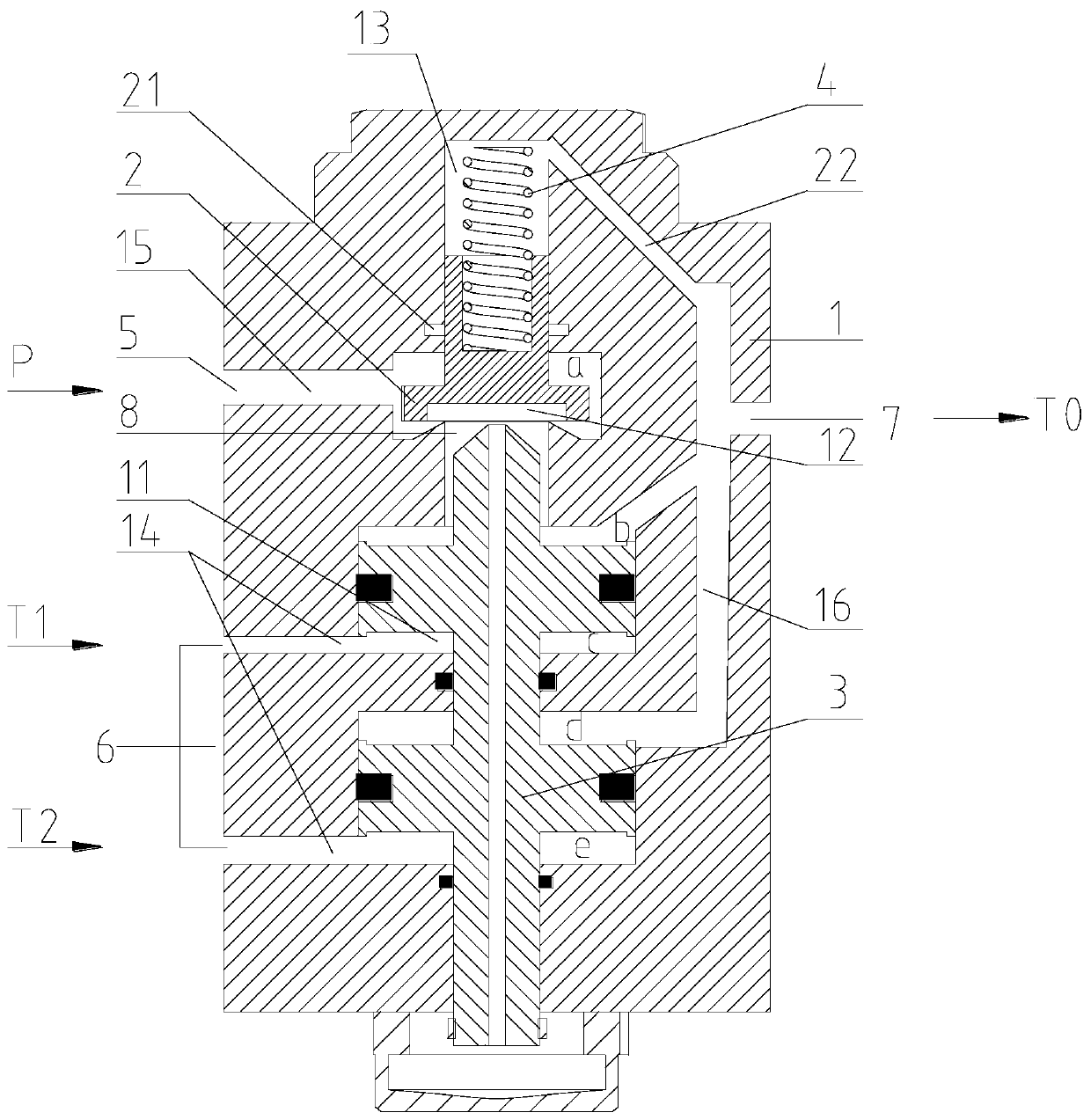
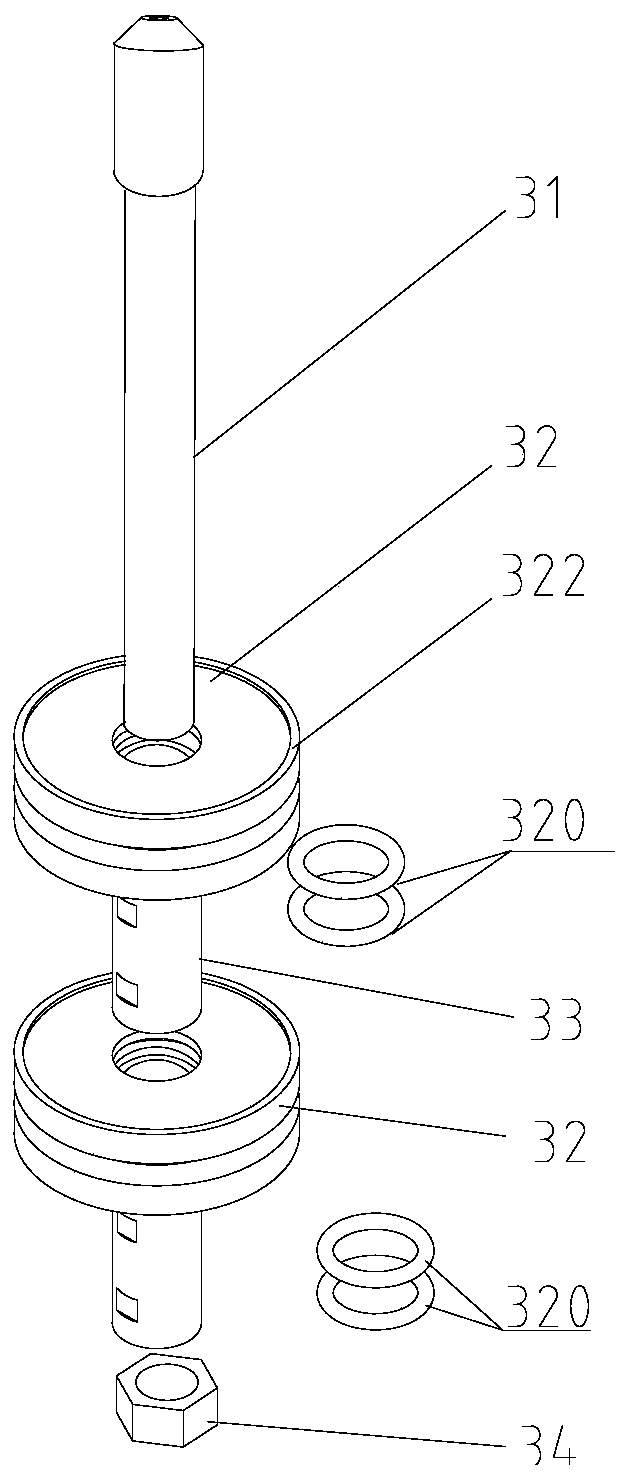
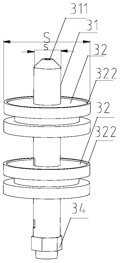
[0031] The present invention provides a multi-gas path averaging valve, which includes a valve body 1, a valve seat 2 and an averaging piston 3. A valve cavity is formed inside the valve body 1, and the averaging piston 3 is arranged in the valve cavity. The averaging piston 3 includes a piston rod 31 and A plurality of piston bodies 32 sleeved and fixed on the piston rod 31, the areas of the piston bodies 32 affected by the air pressure are equal; the side of the piston body 32 away from the valve seat 2 and the inner wall of the va...


PUM


Abstract

The invention discloses a mean valve with multiple air circuits. The mean valve comprises a valve body, a valve seat and a mean piston. A valve cavity is formed in the valve body, the mean piston is arranged in the valve cavity, and the mean piston comprises a piston rod and a plurality of piston bodies, wherein the piston rod is sleeved with the piston bodies, the piston bodies are fixedly arranged on the piston rod, and the areas, under the air pressure action, of the piston bodies are equal. The sides, close to the valve seat, of the piston bodies and the inner wall of the valve body form pressure cavities only communicated with an air pressure inlet channel, and the pressure cavity formed by the side, close to the valve seat, of each piston body and the inner wall of the valve body is connected with a mean pressure outlet. The mean valve is suitable for the mean of two- or more-channel air spring pressure, and it is avoided that when two- or more-channel air spring pressure is processed, a plurality of mean valves need to be connected in parallel or in series, and consequently errors are caused; the concentricity is better, the situations that the friction between the piston and the wall surface of the valve body is enlarged due to overlarge deviations of the concentricity, and the resistance is increased, so that valve action is out of order are avoided.

Description

technical field [0001] The invention relates to the technical field of rail vehicle brake air pressure control valves, in particular to a multi-air path averaging valve. Background technique [0002] The emergency braking force of the rail transit vehicle changes with the change of the load. If the load distribution of the car body is uneven, the real load situation cannot be obtained through the pressure of an air spring. Therefore, in order to weaken the impact of the uneven load, the train brake The control system controls the emergency braking force according to the average pressure of multiple air springs. The averaging valve is mainly used in EMUs and urban rail vehicles. It is a key component of the air suspension control equipment. It can arithmetically average the independent pressure of the air spring, and the output pressure is used as the basis for the brake control system to calculate or adjust the braking force. [0003] At present, the average valves used in ...

Claims


Application Information

Patent Timeline
Patent Type & Authority Patents(China)
IPC IPC(8): F16K11/044F16K1/32F16K1/54F16K31/122
Inventor 刘同新吴学瑞纪铅磊魏灿刚廖志坚涂贵军郗开冲郭宗斌
Owner CRRC QINGDAO SIFANG ROLLING STOCK RES INST
Learn More