Automatic centering system used for track flaw detection and centering detection method thereof

An automatic centering and track technology, which is applied in the field of track flaw detection and displacement sensor, can solve the problems that cannot satisfy the lateral offset detection of track flaw detection, large error of electromagnetic displacement sensor, etc., and achieve high reliability, adjustable detection accuracy, real-time good sex effect

Active Publication Date: 2017-10-24
SHANGHAI ORIENTAL MARITIME ENG TECH CO LTD
View PDF6 Cites 5 Cited by
  • Summary
  • Abstract
  • Description
  • Claims
  • Application Information

AI Technical Summary

Problems solved by technology

At present, the equipment used to detect the lateral offset of the probe wheel position is mainly an electromagnetic displacement sensor, but the electromagnetic displacement sensor can not meet the lateral offset detection in the track flaw detection because it will produce a large error when detecting the track with a large amount of wear. the actual needs of

Method used


Image

  • Automatic centering system used for track flaw detection and centering detection method thereof
  • Automatic centering system used for track flaw detection and centering detection method thereof
  • Automatic centering system used for track flaw detection and centering detection method thereof

Examples


Embodiment 1

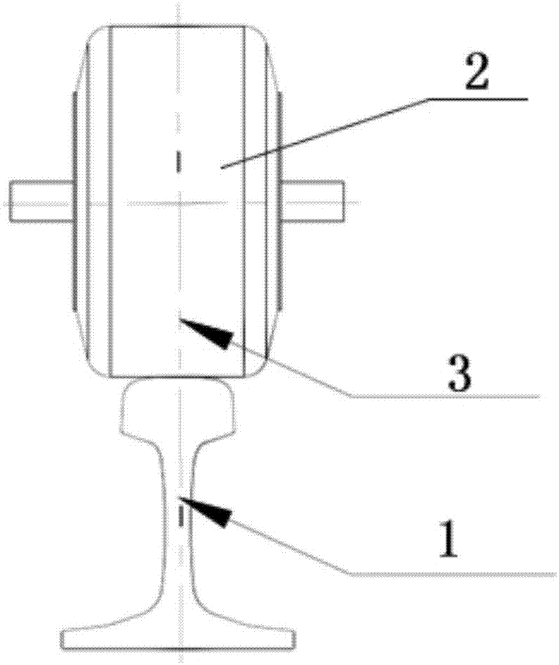
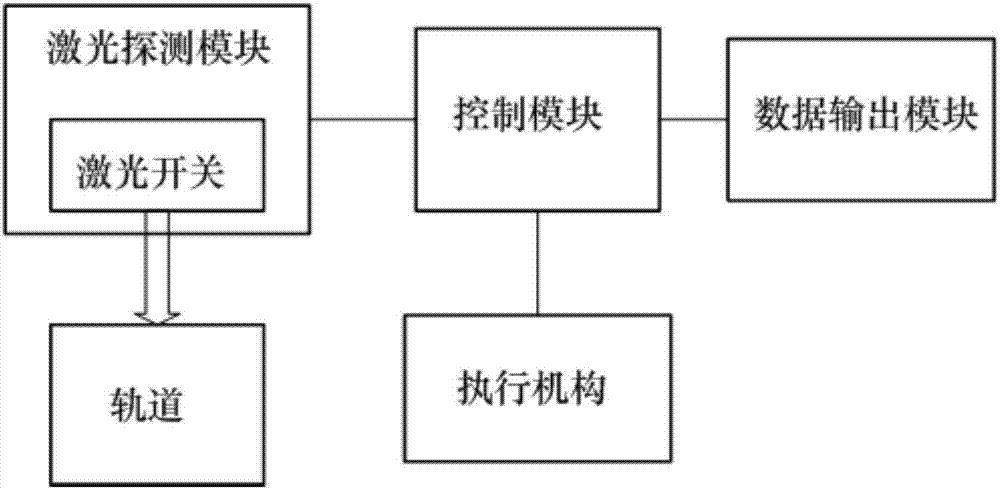
[0036] The invention provides an automatic centering system for rail flaw detection, such as figure 2 As shown, the automatic centering system mainly includes a control module and a laser detection module arranged on the probe wheel 2 . The laser detection module includes a plurality of laser switches 4 arranged at equal intervals, and the control module mainly receives signals from the laser detection module to calculate the horizontal line offset.

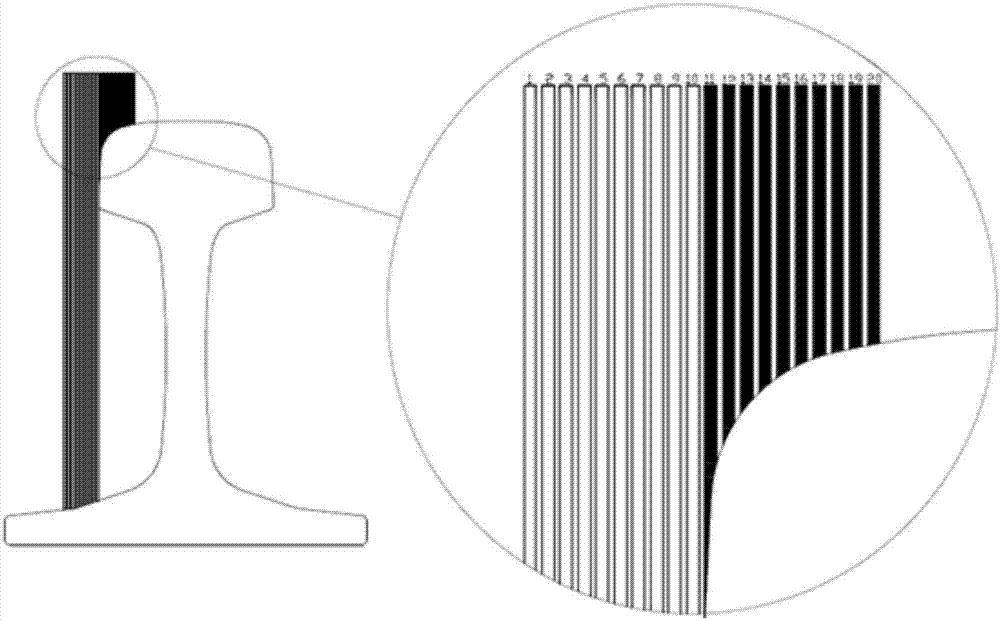
[0037] Specifically, since the laser switch 4 can emit a laser beam to detect whether there is an object in the irradiation place, the laser switches 4 in the laser detection module of the present invention are arranged at equal intervals, and each laser switch 4 can illuminate the tracks parallel to each other and perpendicular to each other. The laser beams of the track, that is, the laser beams emitted by the laser switches 4 are arranged at equal intervals, and the edge of the track is irradiated with parallel laser beams at...

Embodiment 2

[0052] On the basis of the above-mentioned embodiment 1, this embodiment provides the arrangement form of the laser switches 4. The laser switches 4 can be arranged horizontally or obliquely at a certain interval, but it should be noted that for the convenience of calculating the lateral offset No matter whether the laser switches 4 are arranged horizontally or obliquely, it is necessary to ensure that the distance between adjacent laser switches 4 in the horizontal direction is the diameter of the laser beam.

[0053] Such as Figure 5 As shown, adjacent laser switches 4 are arranged laterally at equal intervals on the laser detection module with the diameter of the laser beam as the lateral interval. Since the laser switch 4 itself has a certain size, and the laser switch 4 that is close to each other will generate signal interference, considering the actual application situation, such as Figure 6 As shown, in practical applications, in order to avoid signal interference f...

Embodiment 3

[0055] On the basis of the foregoing embodiment 1 and embodiment 2, this embodiment additionally provides an arrangement form of the laser switches 4 . When the detection range is large, the laser switches 4 arranged according to the arrangement of the laser switches 4 in Embodiment 1 and Embodiment 2 have a wider lateral width. In order to save the space occupied by the laser switches 4, in this embodiment, The laser detection module includes multiple laser switch groups arranged obliquely side by side, and the number of laser switch groups can be selected according to the detection range.

[0056] The number of laser switches 4 in each laser switch group is equal, and the number of laser switches in each laser switch group is multiplied by the laser beam diameter between multiple laser switch groups. At the same time, adjacent laser switches 4 in each laser switch group are arranged obliquely at equal intervals with the laser beam diameter as the transverse interval. At thi...


PUM


Abstract

The invention relates to the technical field of track flaw detection and displacement sensors, and particularly relates to an automatic centering system used for track flaw detection and a centering detection method thereof. The automatic centering system comprises a control module and a laser detection module which is arranged on a wheel detector. The laser detection module comprises multiple laser switches which are equidistantly arranged. Each laser switch irradiates laser beams to the track, and the laser beams are mutually parallel and perpendicular to the track. The laser switches which irradiate to the track and the laser switches which do not irradiate to the track transmit different state values to the control module. The control module calculates the transverse deviation value of the laser detection module relative to the edge of the track according to the state values of all the laser switches. The track is detected by using the laser switches arranged in a spaced way, and the transverse deviation value of the wheel detector relative to the edge of the track is calculated through different state values obtained by the laser switches which irradiate to the track and the laser switches which do not irradiate to the track so that the calculation method is simple, the detection value is accurate, the reliability is high, the stability is high and the real-time performance is great.

Description

technical field [0001] The invention relates to the technical field of rail flaw detection and displacement sensors, in particular to an automatic centering system and a centering detection method dedicated to detecting the deviation between the wheel centerline and the track centerline of a wheeled flaw detection vehicle. Background technique [0002] The ultrasonic wheel-type flaw detection vehicle will produce serpentine motion during the flaw detection process of the rail, which affects the work of the ultrasonic detection wheel, making it difficult to realize high-speed flaw detection. Due to the lateral offset of the detection wheel position, the data collected by the flaw detection vehicle is not accurate. Therefore, it is necessary to limit the lateral offset of the detection wheel within a certain range. At present, the equipment used to detect the lateral offset of the probe wheel position is mainly an electromagnetic displacement sensor, but the electromagnetic di...

Claims


Application Information

Patent Timeline
Patent Type & Authority Applications(China)
IPC IPC(8): G01B11/00B61K9/10
CPCG01B11/00B61K9/10Y02P90/02
Inventor 陈垦匡俊杜新光徐彻林强宋环峰冯兴鹏陆旭红吴毅贤
Owner SHANGHAI ORIENTAL MARITIME ENG TECH CO LTD
Why Eureka
Try Eureka