System for visualizing the cavity-inside microwave ignition and combustion process

A technology of microwave ignition and combustion process, applied in the fields of microwave combustion support and microwave ignition, to achieve the effect of improving fuel utilization rate and combustion quality

Active Publication Date: 2017-10-24
清普莱斯(苏州)环保科技有限公司
View PDF2 Cites 8 Cited by
  • Summary
  • Abstract
  • Description
  • Claims
  • Application Information

AI Technical Summary

Problems solved by technology

[0008] The purpose of the present invention is to solve the problem of visual observation of the microwave ignition process, which can not only realize microwave ignition, but also realize the observation of the development process of microwave ignition by using the schlieren method, and propose a system for realizing the visual observation of microwave ignition and combustion process in the cavity. The invention has the ability to realize microwave resonance ignition, and at the same time meet the requirements of the schlieren method for large-area light transmission, and realize the needs of displaying combustion details, quantitative analysis and calculation, and researching combustion mechanisms

Method used


Image

  • System for visualizing the cavity-inside microwave ignition and combustion process
  • System for visualizing the cavity-inside microwave ignition and combustion process

Examples


Embodiment Construction

[0017] A further description of the visualization observation system for realizing the microwave ignition and combustion process in the cavity proposed by the present invention is as follows with reference to the accompanying drawings.

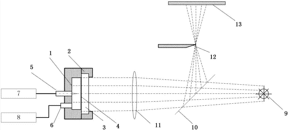
[0018] A schematic diagram of the structure of a system for realizing the visual observation of microwave ignition and combustion process in the cavity proposed by the present invention can be found in figure 2 , the system includes two parts: a microwave ignition device and a microwave ignition visualization device;

[0019] The microwave ignition device includes a U-shaped upper end cover 1, a flat lower end cover 2 with an opening in the middle, quartz glass 3, a microwave coupler 5, a microwave source generator 7, a gas distribution circuit valve 6 and a gas distribution circuit 8; wherein, The upper end cover 1 and the lower end cover 2 are compressed and fixed to form a microwave combustion chamber. The inner side of the top end of the ...


PUM


Abstract

The system for visualizing the cavity-inside microwave ignition and combustion process provided by the present invention belongs to the field of microwave ignition and microwave combustion and includes a microwave ignition device and a microwave ignition visualizing device located on one side of the microwave ignition device. The microwave ignition device comprises a microwave coupler and a gas preparing valve's U-shaped upper cover arranged respectively on the center of the top end and the edge part; a microwave burning chamber formed by a flat lower end cover with a transparent conducting layer of quartz glass on one side embedded right in the center wherein the upper end cover top end's inside is a mirror face. The microwave ignition visualizing device comprises a white light source generator coaxially arranged with the quartz glass, a convex lens, a half-transparent and half-reflective lens, a coaxially arranged knife edge and an imaging screen, wherein the knife edge is located at a focal point where the convex lens is converged with the half-transparent and half-reflective lens. The system can ensure the good reflection characteristic and the microwave resonance mode of the microwave in the cavity, avoids the external leakage of the microwave, and ensures the visible light from the outside to penetrate the cavity. The whole process of the microwave ignition in the combustion cavity is visually observed through the schlieren method.

Description

technical field [0001] The invention relates to a system for realizing the visual observation of the microwave ignition and combustion process in the cavity. Specifically, the pulsed microwave energy is used to generate ignition and combustion in a constant volume combustion cavity of mixed fuel, and the system can be observed and measured. It belongs to microwave Ignition, microwave combustion field. Background technique [0002] At present, the ignition technologies used in internal combustion engines, aero engines, and large combustion furnaces include single-point ignition, spark plug ignition, and microwave ignition. Among them, microwave ignition technology uses microwave radiation and microwave resonance to ignite, which is different from traditional single-point ignition and spark plug ignition. Microwave ignition eliminates the limitations of step-by-step combustion and stratified combustion with low single-point ignition efficiency. The microwave electric field c...

Claims


Application Information

Patent Timeline
Patent Type & Authority Applications(China)
IPC IPC(8): G01M11/00G02B27/00
CPCG01M11/00G02B27/00
Inventor 刘程张贵新谢宏邓磊
Owner 清普莱斯(苏州)环保科技有限公司
Why Eureka
Try Eureka