
Low-torque ripple built-in permanent magnet motor rotor and method for optimizing magnetic flux density of motor

A permanent magnet motor and torque fluctuation technology, which is applied in the manufacture of motor generators, magnetic circuit rotating parts, magnetic circuits, etc., can solve the problem of poor air gap flux density waveform quality, additional cost, and increased stator core and Problems such as rotor core harmonic loss can be achieved to reduce vibration and noise, reduce cogging torque, and reduce harmonic loss

Pending Publication Date: 2017-10-24
TANGSHAN PULIN YIWEI TECH CO LTD
View PDF0 Cites 13 Cited by
  • Summary
  • Abstract
  • Description
  • Claims
  • Application Information

AI Technical Summary

Problems solved by technology

[0002] The air-gap flux density waveform generated by the permanent magnets of the frequency conversion permanent magnet motor is similar to a square wave, which makes the air-gap magnetic field contain a large number of harmonics. When the rotor structure is not designed properly, the harmonic content in the air-gap magnetic field will be more Large, increasing the harmonic loss in the stator core and rotor core, reducing the efficiency of the permanent magnet motor, resulting in poor waveform quality of the air gap flux density
In addition, harmonic currents and harmonic magnetic fields will also generate additional torque fluctuations, which will cause vibration and noise in the motor
Although some other methods can effectively improve the air gap flux density waveform, such as using uneven air gaps, etc., but these methods will increase the difficulty of the process and the man-hours of processing, thereby increasing additional costs

Method used


Image

  • Low-torque ripple built-in permanent magnet motor rotor and method for optimizing magnetic flux density of motor
  • Low-torque ripple built-in permanent magnet motor rotor and method for optimizing magnetic flux density of motor
  • Low-torque ripple built-in permanent magnet motor rotor and method for optimizing magnetic flux density of motor

Examples


Embodiment 1

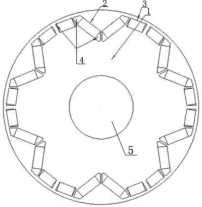
[0023] Embodiment one, with reference to the attached figure 1 .

[0024] A low-torque-fluctuation built-in permanent magnet motor rotor, including a rotor core 1, a permanent magnet, an M-shaped magnetic steel slot 4 and a rotating shaft 5, the permanent magnet is arranged on the rotor core, and the permanent magnet under one magnetic pole is composed of two The one-shaped permanent magnet 3 and one V-shaped permanent magnet 2 are composed, one V-shaped permanent magnet 2 is located in the middle, two in-shaped permanent magnets 3 are respectively located on both sides of the V-shaped permanent magnet 2, and the M Type magnetic circuit structure; 2p M-shaped magnetic steel slots 4 are evenly distributed in a ring on the entire rotor core 1, where p is the number of pole pairs of the permanent magnet motor, two in-line permanent magnets 3 and one V-shaped permanent magnet 2 Set in the M-shaped magnetic steel groove 4. 2p M-shaped magnetic steel slots 4 are evenly distributed...

Embodiment 2

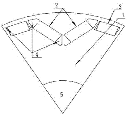
[0031] Embodiment two, referring to the attached figure 2 .

[0032] In this embodiment, the M-shaped magnetic steel groove 4 is composed of four sections, two inline permanent magnets 3 are located in the two sections on both sides, and a V-shaped permanent magnet 2 is located in the middle two sections. The slots are intermittent between segments.

Embodiment 3

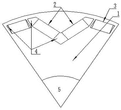
[0033] Embodiment three, with reference to the attached image 3 .

[0034] In this embodiment, the M-shaped magnetic steel groove 4 is composed of four sections, two inline permanent magnets 3 are located in the two sections on both sides, a V-shaped permanent magnet 2 is located in the middle two sections, and two inline permanent magnets 3 are located in the middle two sections. The paragraphs are intermittent and independent, and the middle two paragraphs are continuous, forming a complete V-shape together.


PUM


Abstract

The invention relates to a low-torque ripple built-in permanent magnet motor rotor and a method for optimizing the magnetic flux density of a motor, belonging to the technical field of permanent magnet motors. A permanent magnet under a magnetic pole consists of two line-shaped permanent magnets (3) and one V-shaped permanent magnet (2), the V-shaped permanent magnet (2) is in the middle, and the two line-shaped permanent magnets (3) are arranged at the two sides of the V-shaped permanent magnet to form an M-shaped magnetic circuit structure integrally. 2p M-shaped magnetic steel grooves (4) are uniformly distributed on the whole rotor iron core (1) in a circle, wherein p refers to permanent magnet motor pole pair, and the two line-shaped permanent magnets (3) and the V-shaped permanent magnet (2) are arranged in the M-shaped magnetic steel grooves. By means of the uniform air gap, the manufacturing difficulty of the motor is not increased, the manufacturing technology of the motor is not changed, the harmonic content in the air gap magnetic field can be effectively reduced, the motor harmonic loss can be reduced, the motor efficiency is improved, the motor gullet torque is reduced, and the vibration and noise of the permanent magnet motor is reduced.

Description

technical field [0001] The invention relates to a low-torque fluctuation built-in permanent magnet motor rotor and a method for optimizing the magnetic density of the motor, belonging to the technical field of permanent magnet motors. Background technique [0002] The air-gap flux density waveform generated by the permanent magnets of the frequency conversion permanent magnet motor is similar to a square wave, which makes the air-gap magnetic field contain a large number of harmonics. When the rotor structure is not designed properly, the harmonic content in the air-gap magnetic field will be more Large, increases the harmonic loss in the stator core and rotor core, reduces the efficiency of the permanent magnet motor, and causes the waveform quality of the air gap flux density to deteriorate. In addition, harmonic currents and harmonic magnetic fields will also generate additional torque fluctuations, which will cause vibration and noise in the motor. Although some other m...

Claims


Application Information

Patent Timeline
IPC IPC(8): H02K1/27H02K15/00
CPCH02K1/276H02K15/00Y02T10/64
Inventor 张霄霆姜珊珊赵鹏王小辉孟繁敬
Owner TANGSHAN PULIN YIWEI TECH CO LTD
Learn More