Pattern compound alignment method

A graphic and blind hole technology, applied in electrical components, printed circuit parts, printed circuit manufacturing, etc., can solve problems such as laser hole or mechanical through hole deviation and damage, affect quality, assembly failure, etc., to achieve automatic operation , Reduce poor quality and improve efficiency

Active Publication Date: 2017-10-24
MEIZHOU ZHIHAO ELECTRONICS TECH
View PDF5 Cites 6 Cited by
  • Summary
  • Abstract
  • Description
  • Claims
  • Application Information

AI Technical Summary

Problems solved by technology

[0002] In the process of making printed circuit boards, whether the graphic alignment is accurate or not is a key point related to the quality of circuit board graphics. In the HDI board production process, there are mechanical holes and blind holes at the same time. The traditional technology of only relying on mechanical hole alignment can no longer meet the precision production of blind hole welding rings.
[0003] There are laser holes and mechanical through holes in the HDI board at the same time, and the alignment reference points / equipment precision of the two holes are different. In the line alignment process, there is bound to be a certain difference in the displacement consistency between the two (the difference between the two There is a difference in the expansion and contraction interval), therefore, in the line alignment process, it is difficult to ensure the alignment of the laser hole and the mechanical through hole at the same time, which may easily cause the laser hole or the mechanical through hole to be misaligned and break the ring, directly affecting the quality and scrapping. Seriously directly affect the positioning reference point offset of the electrical measurement process, and the difference between the graphics and the mechanical hole positioning post during SMT assembly, resulting in assembly failure

Method used


Image

  • Pattern compound alignment method
  • Pattern compound alignment method
  • Pattern compound alignment method

Examples


Embodiment Construction

[0037] In order to make the purpose, features and advantages of the present invention more obvious and understandable, the technical solutions in the embodiments of the present invention will be clearly and completely described below in conjunction with the accompanying drawings in the embodiments of the present invention. Obviously, the following The described embodiments are only some, not all, embodiments of the present invention. Based on the embodiments of the present invention, all other embodiments obtained by persons of ordinary skill in the art without making creative efforts belong to the protection scope of the present invention.

[0038] The technical solutions of the present invention will be further described below in conjunction with the accompanying drawings and through specific implementation methods.

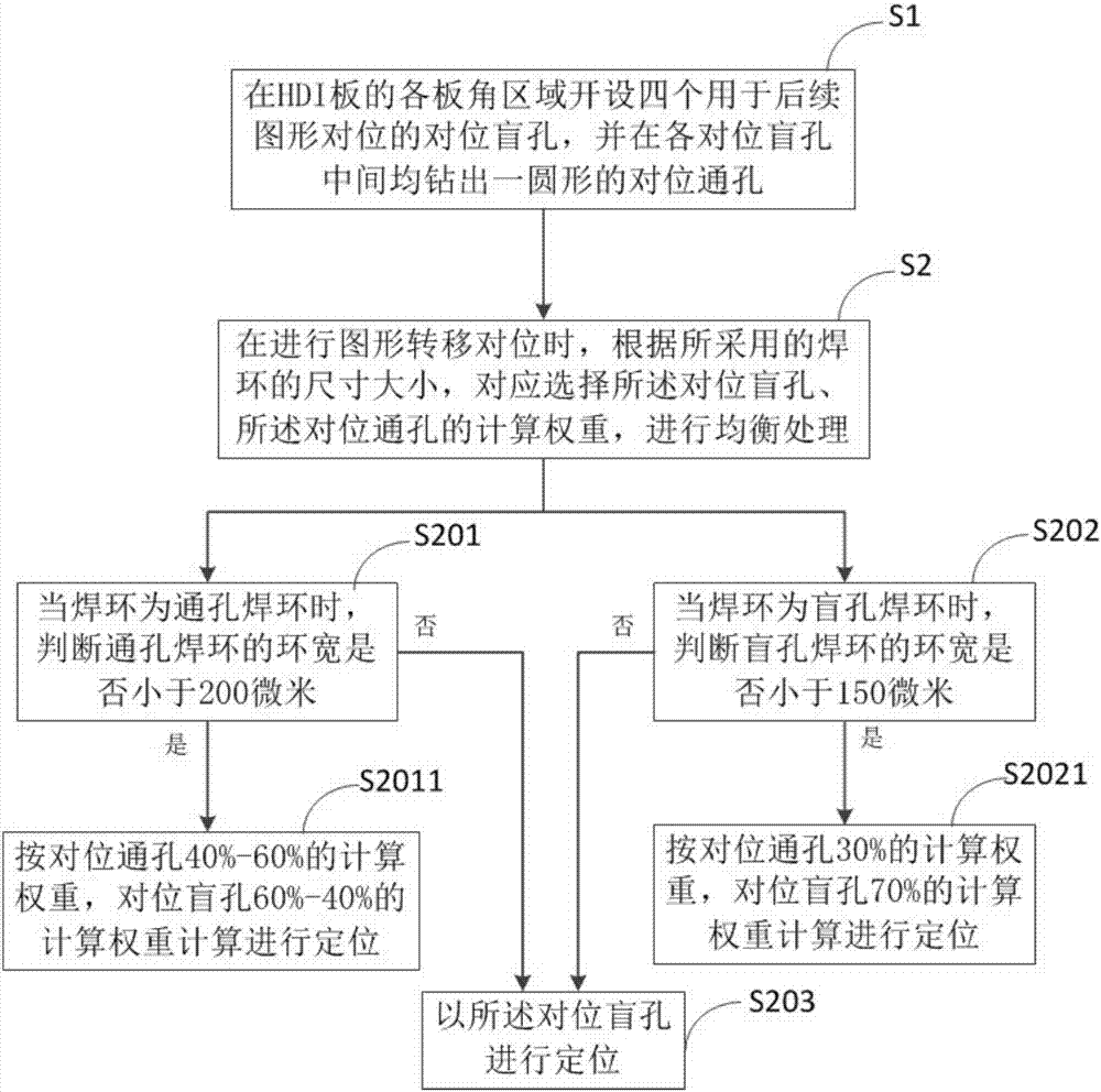
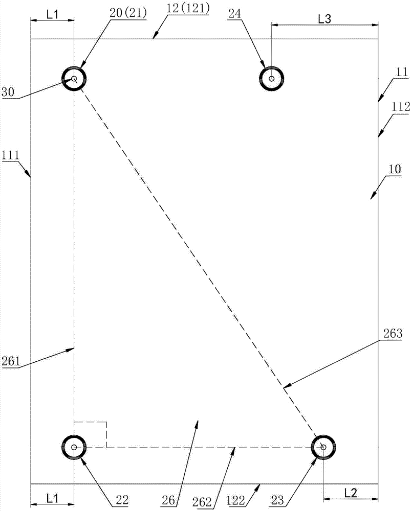
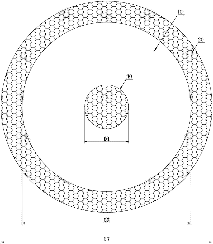
[0039] Please refer to figure 1 and figure 2 , figure 1 It is a flow chart of a graphic compound alignment method provided by an embodiment of the present ...


PUM


Abstract

The invention discloses a pattern compound alignment method, and the method comprises the steps: four alignment blind holes for following pattern alignment are arranged on corner areas of an HDI board, a circular alignment through hole is arranged on each center of the alignment blind holes, when pattern transferring alignment is performed, calculation weights of the alignment blind holes and the alignment through holes are correspondingly selected according to sizes of adopted welding rings, and balanced-processing is performed, wherein the welding rings include blind hole welding rings and through hole welding rings. According to the invention, through hole alignment targets and blind hole alignment targets are mixed in alignment targets, when pattern alignment is performed, two kinds of alignment targets are captured to balance alignment bias caused by two kinds of hole types, the pattern alignment efficiency is greatly improved, poor quality is reduced, alignment precision is improved, a pattern target fused with plate edge design of an HDI product is added to a design operation module, and automatic operation is realized.

Description

technical field [0001] The invention relates to the technical field of mechanical drilling rigs, in particular to a pattern composite alignment method. Background technique [0002] In the process of making printed circuit boards, whether the graphic alignment is accurate or not is a key point related to the quality of circuit board graphics. In the HDI board manufacturing process, there are mechanical holes and blind holes at the same time, and the traditional technology of only relying on mechanical hole alignment can no longer meet the precision production of blind hole welding rings. [0003] There are laser holes and mechanical through holes in the HDI board at the same time, and the alignment reference points / equipment precision of the two holes are different. In the line alignment process, there is bound to be a certain difference in the displacement consistency between the two (the difference between the two There is a difference in the expansion and contraction int...

Claims


Application Information

Patent Timeline
Patent Type & Authority Applications(China)
IPC IPC(8): H05K3/00H05K1/02
CPCH05K1/0266H05K3/0026H05K2203/107H05K2203/166
Inventor 罗登峰刘喜科戴晖
Owner MEIZHOU ZHIHAO ELECTRONICS TECH
Why Eureka
Try Eureka