A method of using a trailer frame component assembly and welding system

A welding system and component technology, applied in welding equipment, welding equipment, vehicle components, etc., can solve problems such as potential safety hazards, frame assembly errors, and low weld strength, so as to avoid potential safety hazards, prevent bump deformation, reduce The effect of labor intensity

Active Publication Date: 2019-03-29
江苏富华交通运输设备股份有限公司
View PDF5 Cites 0 Cited by
  • Summary
  • Abstract
  • Description
  • Claims
  • Application Information

AI Technical Summary

Problems solved by technology

[0005] Due to the long front and rear dimensions of the overall workpiece of the frame assembly, large volume, many welds, and high welding quality requirements for the welds, the assembly and welding of the trailer frame assembly is usually carried out step by step at present, that is, first according to the parts. Assemble and weld separately, then integrate and assemble each part, and finally perform integrated welding. In the process of integrating, assembling and welding, in order to prevent welding deformation, it usually needs to be turned over multiple times with the whole body. This traditional assembling and welding method usually cannot be realized in The entire weld seam in the front and rear direction, so the strength of the weld seam is relatively low; and if the welding deformation occurs during the welding process of each component in the step-by-step assembly welding method, it is easy to produce cumulative errors in the integrated welding process, which is easy to cause the frame The shape and position errors such as the overall tilt adjustment of the components; in addition, the large frame volume makes it difficult to turn over, which not only easily causes the lifting to fall apart, but also poses safety hazards

Method used


Image

  • A method of using a trailer frame component assembly and welding system
  • A method of using a trailer frame component assembly and welding system

Examples


Embodiment Construction

[0027] The present invention will be further described below in conjunction with accompanying drawing (be described ahead with the traction direction of tractor below).

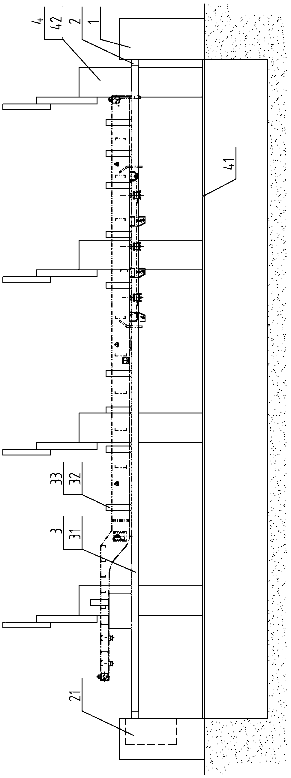
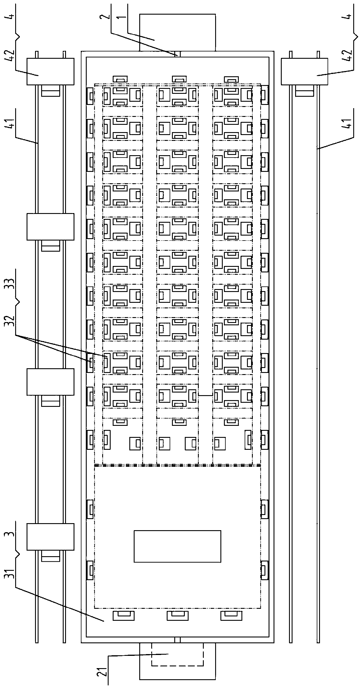
[0028] Such as figure 1 , figure 2 As shown, the trailer frame assembly assembly welding system used in the method of using the trailer frame assembly assembly welding system includes a support frame 1, a turning shaft 2, a workpiece support part 3 and an electric control device.

[0029] The support frame 1 is symmetrically arranged in two pieces in the front and back directions, and is fixedly installed on the ground.

[0030] Described overturning shaft 2 is arranged as two pieces, and two overturning shafts 2 are concentrically arranged, and one end of two overturning shafts 2 is installed on the upper inner surface of support frame 1 through the bearing seat, and at least one overturning shaft 2 is provided with The supporting frame 1 or the overturning drive device 21 on the ground can drive the over...


PUM


Abstract

The invention discloses a usage method of a trailer frame assembly splicing and welding system. The usage method comprises the steps of splicing point preparation, point splicing and welding of I-steel girders, point splicing and welding of cross beams, point splicing and welding of side beams, overall hoisting and the like. The usage method of the trailer frame assembly splicing and welding system uses the upper surfaces of horizontal flat slab structure workpiece supporting plates as point splicing reference surfaces, a positioning device and a pressing device are utilized to sequentially position and press parts of frame assembly workpieces on the upper surface of workpiece supporting plates, accurate position location of the parts before point splicing can be ensured, the workpiece supporting plates can be overturned by controlling an overturning drive device along axes of driving overturning shafts at set angles during point splicing or welding, thus reduction of the labor intensity of an operator is achieved, and bumping deformation of the frame assembly workpieces is prevented. Overturning of the frame assembly workpieces is not needed after dismounting in the splicing-welding process, the potential safety hazard of likely occurred apart falling during hoisting or overturning is avoided, and the point splicing and welding efficiency is higher.

Description

technical field [0001] The invention relates to a method for using an assembly welding system, in particular to a method for using an assembly welding system suitable for trailer frame components, and belongs to the technical field of trailers. Background technique [0002] A trailer refers to a vehicle that is towed by a car and has no power drive itself. It can usually be a car train composed of a tractor (truck or tractor, forklift, etc.) and one or more trailers. The car train belongs to the category of cars. The use of automobile and train transportation is the most effective and simple important means to improve economic benefits. It has the advantages of rapidity, maneuverability, flexibility and safety, and can conveniently realize section transportation. [0003] Trailers are divided into full trailers and semi-trailers according to the connection method between the trailer and the tractor. The full trailer is pulled by the tractor and its entire mass is borne by it...

Claims


Application Information

Patent Timeline
Patent Type & Authority Patents(China)
IPC IPC(8): B23K37/047B23K31/00B23K101/00
CPCB23K31/003B23K37/047B23K2101/006
Inventor 解庆佳
Owner 江苏富华交通运输设备股份有限公司
Why Eureka
Try Eureka