Auxiliary lifting device for material processing

An auxiliary lifting and material processing technology, applied in metal processing equipment, grinding/polishing equipment, manufacturing tools, etc., can solve the problems of wallboard burrs, time-consuming and laborious, and heavy burden on the waist of the staff, so as to reduce occupational diseases and facilitate use , the effect of liberating manpower

Inactive Publication Date: 2017-10-27
肇庆市智高电机有限公司
View PDF6 Cites 15 Cited by
  • Summary
  • Abstract
  • Description
  • Claims
  • Application Information

AI Technical Summary

Problems solved by technology

[0013] At present, in the indoor high-altitude operations in the construction and decoration market, scaffolding and self-made wooden ladders are still mainly used; taking plastering and powder walls as an example, a single construction worker cannot take care of the upper and lower working surfaces, and the construction workers on the scaffold need other personnel to assist To move the construction ashes, the construction workers under the scaffold need to lean over to pick up the construction ashes hundreds of times a day, so auxiliary equipment such as scaffolding and wooden ladders cannot realize the automation of building material transfer
[0014] Nowadays, with the continuous improvement of people's living standards, people's use of items is also increasing. Wall panels are one of the items that people need for home decoration. When wall panels are reproduced, burrs and irregular bumps will appear on the wall panels. In order to solve this problem, grinding will be carried out. When grinding, due to the different heights of people, too high is not conducive to grinding and polishing, and too low is too much. When going up and down frequently at different heights, and frequently moving the working point in a certain range, how I wish there is a ladder that can move and lift automatically, so that they can solve their troubles of frequently going up and down and moving the ladder, and reduce the labor intensity for them. work efficiency

Method used

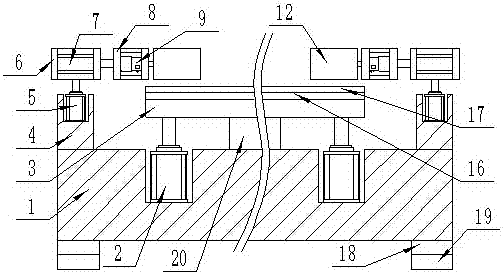
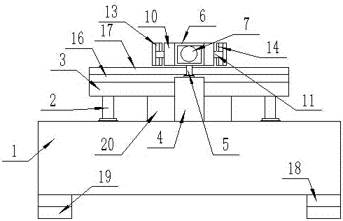
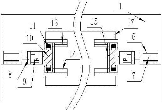

Image

  • Auxiliary lifting device for material processing
  • Auxiliary lifting device for material processing
  • Auxiliary lifting device for material processing

Examples


Embodiment Construction

[0029] The following will clearly and completely describe the technical solutions in the embodiments of the present invention with reference to the accompanying drawings in the embodiments of the present invention. Obviously, the described embodiments are only some, not all, embodiments of the present invention. Based on the embodiments of the present invention, all other embodiments obtained by persons of ordinary skill in the art without making creative efforts belong to the protection scope of the present invention.

[0030]In describing the present invention, it should be understood that the terms "center", "longitudinal", "transverse", "upper", "lower", "front", "rear", "left", "right", " The orientations or positional relationships indicated by "vertical", "horizontal", "top", "bottom", "inner" and "outer" are based on the orientations or positional relationships shown in the drawings, and are only for the purpose of describing the present invention and simplify the desc...


PUM


Abstract

The invention discloses an auxiliary lifting device for material processing, which comprises a base, and two pairs of cylinder placement grooves are opened on the upper wall of the base, and the first hydraulic cylinder with the telescopic end facing upward is fixed in the cylinder placement groove, and the two pairs of cylinder placement grooves are fixed in the cylinder placement grooves. The telescopic end of the first hydraulic cylinder is fixed to the supporting plate, and a pair of installation rods are fixed on the upper wall of the base and located on both sides of the two pairs of cylinder placement grooves. End up second hydraulic cylinder. According to the invention, the workers can be adjusted at will according to their own heights, which is convenient for people to grind, and reduces the occurrence of occupational diseases of the workers. The automatic lifting, stepping up, rotating and changing surfaces can liberate manpower and is convenient to use.

Description

technical field [0001] The invention relates to the field of material processing, in particular to an auxiliary lifting device for material processing. Background technique [0002] With the continuous growth of the national economy and the continuous improvement of people's living standards, people pay more and more attention to the quality of the living environment. my country is a country with a large population, and the proportion of urban population is 45%. In recent years, the real estate industry in various cities in my country has developed rapidly. Residential buildings have sprung up like mushrooms after rain. The huge market temptation is doomed to the rapid development of the decoration design industry and various new decoration materials are pushed to the market like a tide. Due to the continuous improvement of people's requirements for the appearance and interior of buildings, the proportion of decoration in the entire project cost has been continuously incre...

Claims


Application Information

Patent Timeline
Patent Type & Authority Applications(China)
IPC IPC(8): B24B41/06B24B47/00B24B9/18
CPCB24B41/068B24B9/18B24B47/00
Inventor 陈彬强蔡勇
Owner 肇庆市智高电机有限公司
Why Eureka
Try Eureka