Laminating device used for identifying labels and operation method of laminating device

A technology of laminating device and signs, applied in the field of sign sign processing, can solve the problems of high labor intensity for operators, easy damage to the surface of sign signs, and low quality of film, so as to improve film efficiency, avoid damage, and improve film cover. Effect of Membrane Quality

Inactive Publication Date: 2017-10-27
ANHUI STARLIGHT LOGO SYST CO LTD
View PDF13 Cites 12 Cited by
  • Summary
  • Abstract
  • Description
  • Claims
  • Application Information

AI Technical Summary

Problems solved by technology

[0003] The purpose of the present invention is to provide a reasonable structural design, applicable Film laminating device for label label and operation method thereof with wide range, high work efficiency, good film quality, good label label integrity, and low operator labor intensity

Method used


Image

  • Laminating device used for identifying labels and operation method of laminating device
  • Laminating device used for identifying labels and operation method of laminating device
  • Laminating device used for identifying labels and operation method of laminating device

Examples


Embodiment 1

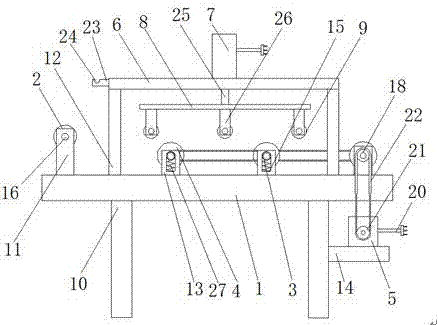
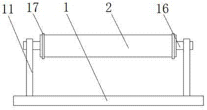
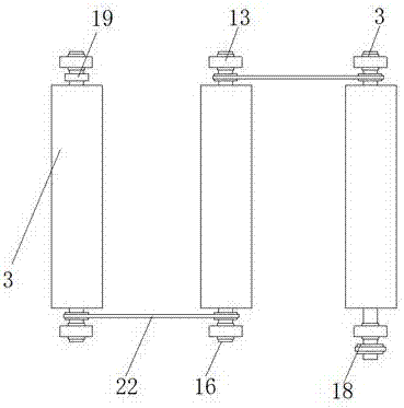
[0028] as attached Figure 1-4 As shown, a film laminating device for marking signs includes an operation table 1, a guide roller 2, a shaft sleeve 3, a drive roller 4, a motor 5, a top plate 6, a cylinder 7, an adjustment plate 8 and a pressure roller 9, and its characteristics In that: the console 1 is set on the support 10, and the console 1 is provided with a fixed plate 11, a column 12, a vertical plate 13, the support 10 is provided with a bearing plate 14, the vertical plate 13 is provided with a limit groove 15, the guide roller 2 is arranged between the fixed plate 11 and the fixed plate 11 through the connecting shaft 16, the shaft sleeve 3 is arranged in the limit groove 15, and the transmission roller 4 Both ends are provided with connecting shaft 16, the connecting shaft 16 is arranged in the axle sleeve 3, and the driving wheel 18 and the driven wheel 19 are arranged on the connecting shaft 16 of the drive roller 4, and the described motor 5 is arranged on the be...

Embodiment 2

[0043] as attached Figure 5 As shown, a film laminating device for marking signs includes an operation table 1, a guide roller 2, a shaft sleeve 3, a drive roller 4, a motor 5, a top plate 6, a cylinder 7, an adjustment plate 8 and a pressure roller 9, and its characteristics In that: the console 1 is set on the support 10, and the console 1 is provided with a fixed plate 11, a column 12, a vertical plate 13, the support 10 is provided with a bearing plate 14, the vertical plate 13 is provided with a limit groove 15, the guide roller 2 is arranged between the fixed plate 11 and the fixed plate 11 through the connecting shaft 16, the shaft sleeve 3 is arranged in the limit groove 15, and the transmission roller 4 Both ends are provided with connecting shaft 16, the connecting shaft 16 is arranged in the axle sleeve 3, and the driving wheel 18 and the driven wheel 19 are arranged on the connecting shaft 16 of the drive roller 4, and the described motor 5 is arranged on the bear...


PUM


Abstract

The invention discloses a laminating device used for identifying labels. The laminating device comprises a control console, a guide roller, bushings, transmission rollers, a motor, a top plate, an adjusting plate and a press roller and is characterized in that the operating console is arranged on a support, a bearing plate is arranged on the support, limit slots are arranged in vertical plates, the guide roller is arranged between fixing plates through a connecting shaft, the bushings are arranged in the corresponding limit slots, the connecting shafts are arranged at two ends of the transmission rollers, the motor is arranged on the bearing plate, the top plate is arranged on uprights, an air cylinder is arranged on the top plate, the adjusting plate is arranged on a piston rod, a positioning plate is arranged on the adjusting plate, and the press roller is arranged between positioning plates through the connecting shafts. The guide roller is arranged between the fixing plates, partition plates are arranged on the guide roller and can prevent a thin film skewing on the guide roller, and laminating quality in identifying the labels is improved.

Description

technical field [0001] The invention relates to the technical field of signage processing, in particular to a film coating device for signage and an operating method thereof. Background technique [0002] After the identification label is processed, in order to prevent the identification label from being damaged during transportation, a layer of film will be covered on the surface of the identification label. The existing identification label film coating device has the disadvantages of low work efficiency and low film quality. , such as the patent application No. 201420385410.8, which discloses a logo label laminating machine, which solves the problem that the logo label cannot be moved during the lamination process, but it has low work efficiency, high labor intensity for operators, and poor film quality. It is not high enough, and the surface of the identification plate is easily damaged. Contents of the invention [0003] The purpose of the present invention is to pro...

Claims


Application Information

Patent Timeline
Patent Type & Authority Applications(China)
IPC IPC(8): B65B33/02
CPCB65B33/02
Inventor 张建新邹佳玲倪成亮
Owner ANHUI STARLIGHT LOGO SYST CO LTD
Why Eureka
Try Eureka