

Large shaft end keyway electrolytic machining device
A technology for machining devices and shaft parts, which is applied in the field of electrolytic machining devices, can solve the problems of no large-scale shaft part end keyway electrolytic machining devices, etc., and achieve the effects of simple structure, strong applicability, reliability and good quality
- Summary
- Abstract
- Description
- Claims
- Application Information
AI Technical Summary
Problems solved by technology
Method used
Image

Examples
Embodiment Construction
[0034] Preferred embodiments of the present invention will be described in detail below in conjunction with the accompanying drawings.
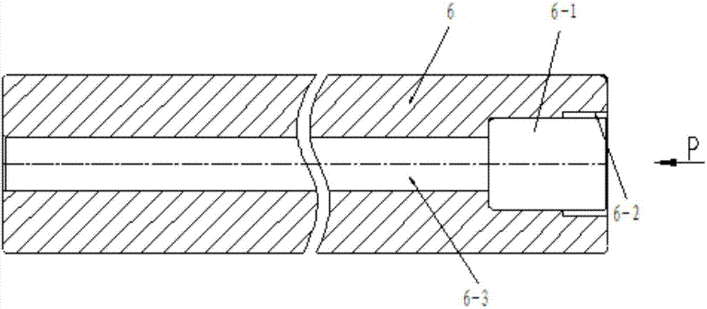
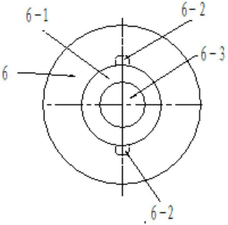
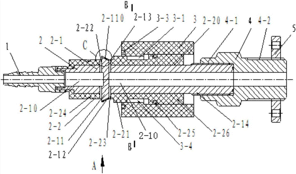
[0035] see Figure 3 to Figure 7 , the electrolytic machining device of the large shaft end keyway of the present invention includes a hose joint 1, an electrolytic cathode 2, a sealing sleeve 3, a connecting head 4 and a flange 5. Depend on Figure 3 to Figure 7It can be seen that the electrolysis cathode 2 includes a copper body 2-1 and an insulating guide body 2-2; the copper body 2-1 is provided with; the axial hole 2-10 is located in the copper body integrally with the copper body 2-1 2-1 The isolation part 2-11 on the left side that separates the axial hole 2-10, the outer surface extending symmetrically and radially outward from the isolation part 2-11 is covered with an insulating layer 2-12, and is electrolytically processed The two bosses 2-110 on the two end key grooves 6-2 on the large-scale shaft part 6 are adapted to the circu...
PUM
 Abstract
Description
Claims
Application Information