Positioning mechanism switching device and assembly line

A switching device and positioning mechanism technology, applied in auxiliary devices, motor vehicles, transportation and packaging, etc., can solve problems such as lifting and unfavorable automation efficiency, and achieve the effect of convenient switching and convenient function switching

Pending Publication Date: 2017-11-03
宜兴东方智能汽车装备有限公司
View PDF0 Cites 0 Cited by
  • Summary
  • Abstract
  • Description
  • Claims
  • Application Information

AI Technical Summary

Problems solved by technology

[0003] At present, one model is processed in one line, or a separate positioning method is used, which is not conducive to the improvement of automation efficiency

Method used


Image

  • Positioning mechanism switching device and assembly line
  • Positioning mechanism switching device and assembly line
  • Positioning mechanism switching device and assembly line

Examples


Embodiment 1

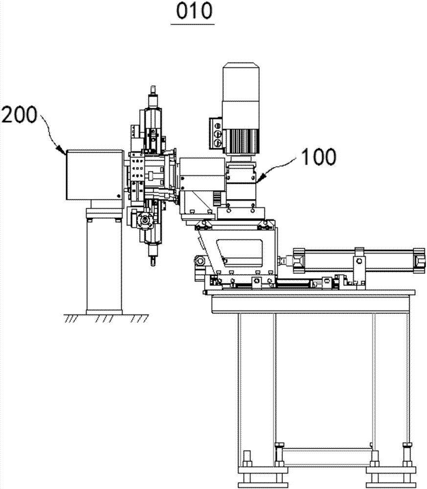
[0047] figure 1 It is a structural schematic diagram of the positioning mechanism switching device 010 in Embodiment 1 of the present invention. Please refer to figure 1 , the positioning mechanism switching device 010 in this embodiment includes a switching device 100 and a positioning device 200 .

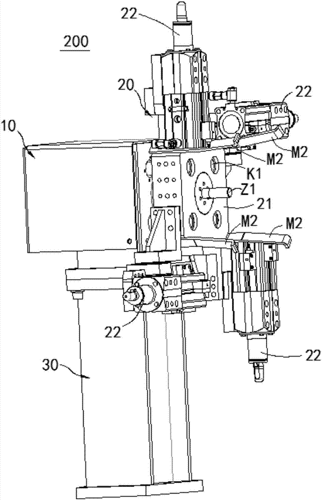
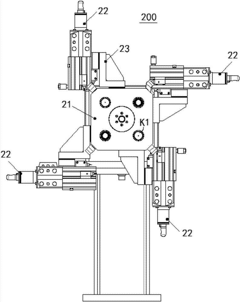
[0048] figure 2 , image 3 , Figure 4 The positioning device 200 in this embodiment is shown at different angles. See figure 2 (for coordination see image 3 , Figure 4), the positioning device 200 includes a fixed seat 10, a positioning plate 20, and a base 30. The fixing base 10 is installed on the upper end of the base 30 , and the positioning plate 20 is rotatably connected to the side of the fixing base 10 . During normal use, the rotation between the positioning disc 20 and the fixed seat 10 is locked and limited, and the rotation restriction between the positioning disc 20 and the fixed seat 10 can be unlocked when necessary. The specific structure and method ...

Embodiment 2

[0069] See Figure 11 , Figure 12 , the embodiment of the present invention provides an assembly line 001, which includes a transmission line 300 and at least one positioning mechanism switching device 010 in the first embodiment. The positioning device 200 of the positioning mechanism switching device 010 is disposed on the transmission line 300 , and the switching device 100 is opposite to the positioning device 200 .

[0070] By setting the positioning mechanism switching device 010 in the first embodiment on the transmission line 300, the automatic switching of the positioner 22 of some processes (such as welding, etc.) on the assembly line 001 can be realized, so that the assembly line 001 can automatically adapt to different to-be-assembled Fittings, assembly in different assembly positions.


PUM


Abstract

The invention relates to the field of assembly lines, and aims to solve the problem that the existing positioning mechanism is inconvenient to switch and cannot adapt to the positioning of different vehicle models on the assembly line, and provides a positioning mechanism switching device and an assembly line. The positioning mechanism switching device switches the device and the positioning device. The positioning device includes a fixing seat and a positioning plate. The positioning plate includes a switching plate and a plurality of positioners. The switching disc is rotatably connected to the fixing base. The switch disc is provided with a rotation limiting through hole, and the fixing seat has a rotation limiting rod that can extend axially and be inserted into the rotation limiting through hole to lock the switching disc. The switching device includes a linear drive, a rotary drive, and a switching head. The switching head includes a torque rod. Rotary drive transmission connection switching head. A linear drive transmission is connected to a rotary drive. The beneficial effect of the invention is that it can conveniently realize the switching of the locator, facilitate the function switching of the automatic assembly line, and make the assembly line conveniently applicable to different vehicle types.

Description

technical field [0001] The invention relates to the field of assembly lines, in particular to a positioning mechanism switching device and an assembly line. Background technique [0002] On the automobile production and assembly line, it is often encountered that one line has to deal with multiple models. The switching process, such as the welding process, requires positioning of the vehicle, which requires different positioning devices. [0003] At present, one model is processed in one line, or a separate positioning method is used, which is not conducive to the improvement of automation efficiency. Contents of the invention [0004] The present invention aims to provide a positioning mechanism switching device to solve the above problems. [0005] Another object of the present invention is to provide an assembly line equipped with the above positioning mechanism switching device. [0006] Embodiments of the present invention are achieved like this: [0007] A positio...

Claims


Application Information

Patent Timeline
Patent Type & Authority Applications(China)
IPC IPC(8): B23K37/04B23K37/00B62D65/02
CPCB23K37/0426B23K37/00B23K2101/006B62D65/024
Inventor 陈古亚
Owner 宜兴东方智能汽车装备有限公司
Why Eureka
Try Eureka