Optical cable and electric cable laying method applicable to intelligent substation

A smart substation and cable laying technology, which is applied in the direction of cable laying equipment, etc., can solve the problems of large floor area and one-time cost investment, inability to effectively avoid cable crossing, poor maintainability, etc., and achieve optimal fire prevention effects and construction procedures. Well-ventilated, easy-to-replace effect

Inactive Publication Date: 2017-11-03
JIAXING HENGCHUANG ELECTRIC POWER DESIGN & RES INST CO LTD +1
View PDF6 Cites 0 Cited by
  • Summary
  • Abstract
  • Description
  • Claims
  • Application Information

AI Technical Summary

Problems solved by technology

Compared with direct burial laying and pipe laying, cable trench laying occupies a larger area and one-time investment; there is also a type of pipe laying. Compared with direct burial laying, the land for pipe laying is larger and the cost is higher; Compared with the laying of cable trenches, when laying pipes, the cables must be laid according to the specified pipe holes, and the crossing of cables cannot be effectively avoided.
However, both of these two laying methods have the disadvantages of inflexible structure and poor maintainability.

Method used


Image

  • Optical cable and electric cable laying method applicable to intelligent substation

Examples


Embodiment Construction

[0042] The present invention will be described in detail below in conjunction with the accompanying drawings and embodiments.

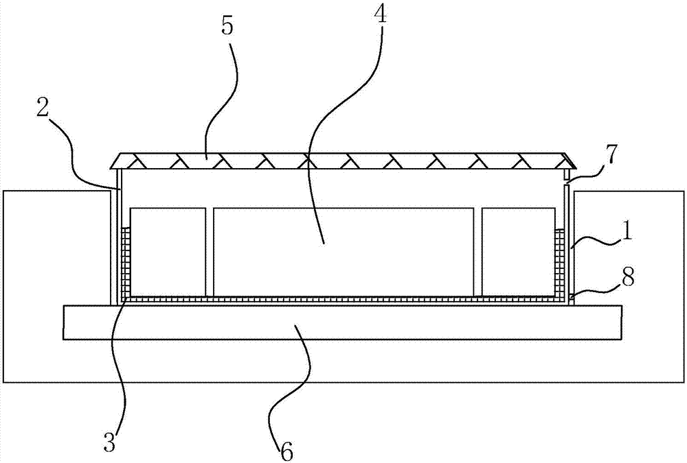
[0043] Optical cables and cable laying methods applied to smart substations, the specific steps are as follows:

[0044] Step a. Ground trenching: According to the design drawing, measure the center line of the trench 1, set up the center pile, draw the line with a white line before excavation, set control piles on both sides of the foundation pit position and record the distance between the two piles and the center of the foundation pit. After the white line is positioned, the trencher is used to excavate the earthwork until the design elevation is reached, and the foundation pit can be obtained. The cable or optical cable is laid on the ground as required, and then the trench is excavated. Trough 1 is leveled; compared with the traditional cable laying method, this method requires shallower trenching, less earthwork excavation, no embedded parts, sh...


PUM


Abstract

The invention discloses an optical cable and a cable laying method applied to an intelligent substation, aiming to solve the problems of inflexible structure and poor maintainability during traditional cable laying. The key points of the technical solution are step a, ground ditching; step b, outer Laying of tank boxes; step c, laying of supporting bridges; step d, laying of inner tank boxes; step e, laying power cables, control cables and optical cables in three groups of inner tank boxes; step f, inner layer tank boxes at branches Laying; step g, the tank box is closed. The optical cable and cable laying method applied to the intelligent substation of the present invention have more flexible installation structure and strong maintainability.

Description

technical field [0001] The invention relates to the field of cable construction methods, more specifically, it relates to an optical cable applied to an intelligent substation and a cable laying method. Background technique [0002] Cable trench laying refers to the installation method of laying cables in pre-built cable trenches. In terms of structural characteristics, the cable adopts a concrete or brick structure, the top is covered with a cover plate, and a single-side or double-side support is provided in the ditch. The cable trench cover inside the house is level with the floor; the cable trench cover outside the house is higher than the ground and can also be used for operation. Compared with direct burial laying and pipe laying, cable trench laying occupies a larger area and one-time investment; there is also a type of pipe laying. Compared with direct burial laying, the land for pipe laying is larger and the cost is higher; Compared with cable trench laying, when ...

Claims


Application Information

Patent Timeline
IPC IPC(8): H02G1/06
CPCH02G1/06
Inventor 仇群辉张森海徐伟明沙磊朱少华陆恩灏倪瑞君何平宋同徐杰章思亮沈毓陈兵强
Owner JIAXING HENGCHUANG ELECTRIC POWER DESIGN & RES INST CO LTD
Why Eureka
Try Eureka