Self-powered ship-borne positioning and tracking device

A positioning tracking, self-powered technology, applied in electromechanical devices, electrical components, generators/motors, etc., to achieve the effects of high reliability, strong environmental adaptability, and effective frequency bandwidth

Active Publication Date: 2017-11-03
ZHEJIANG NORMAL UNIVERSITY
View PDF5 Cites 6 Cited by
  • Summary
  • Abstract
  • Description
  • Claims
  • Application Information

AI Technical Summary

Problems solved by technology

[0003] Aiming at some problems existing in the use and power supply of the existing ship monitoring system, the present invention proposes a ship-borne self-powered positioning and tracking device

Method used


Image

  • Self-powered ship-borne positioning and tracking device
  • Self-powered ship-borne positioning and tracking device

Examples


Embodiment Construction

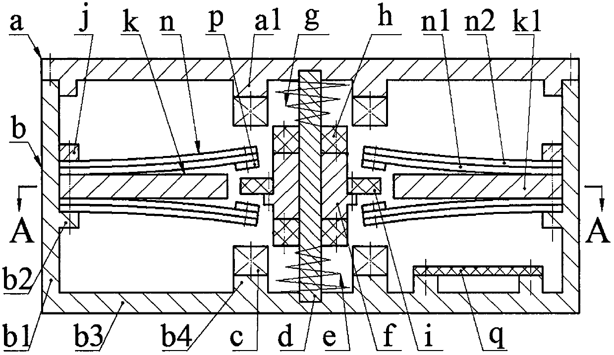
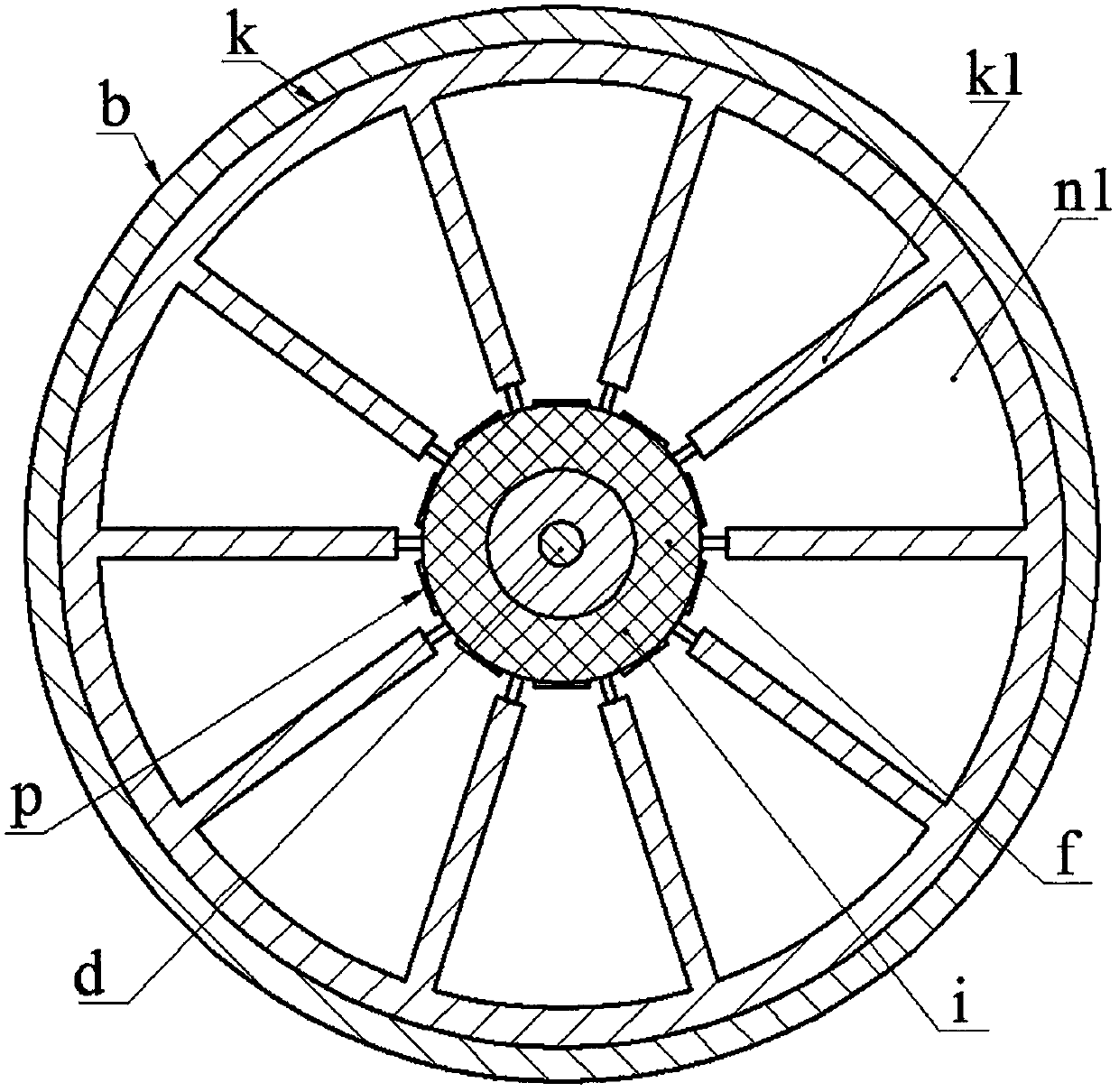
[0009] The upper cover a is installed on the end of the cylinder wall b1 of the shell b through screws, and the cylinder wall b1 is provided with a cylinder wall boss b2; the boss a1 of the upper cover a and the boss b4 of the bottom wall b3 of the shell are both screwed A coil c is installed; both ends of the guide post d are respectively fixed on the upper cover a and the bottom wall b3 of the housing, and the guide post d is sequentially covered with a balance spring e, an inertia block f and a limit spring g, and the balance spring e And the limit spring g is a disc spring, the upper and lower ends of the inertia block f are installed with a generator magnet h through screws, and the side is installed with a suspension magnet i through screws; the upper surface of the generator magnet h above the inertia block f and its adjacent coil The lower surface of c is located on the same plane, the lower surface of the electromagnet f under the inertia block f and the upper surface ...


PUM


Abstract

The invention relates to a self-powered ship-borne positioning and tracking device and belongs to the technical field of ship electronics. An upper cover is arranged on an end part of a cylinder wall of a shell body, the upper cover and a boss of a bottom wall of the shell body are provided with wire coils; two ends of a guide column are fixed on the upper cover and the bottom wall of the shell body; a balance spring, an inertia block and a limiting spring orderly sleeve the guide column; an upper end and a lower end of the inertial block are provided with power generation magnets and sides are provided with suspension magnets; two groups of energy transducers are uniformly arranged on a boss of the cylinder wall through a compression ring and a spacer ring, and spacing discs are uniformly arranged on the spacer ring; the two groups of energy transducers are symmetrically arranged on an upper side and a lower side of the spacer ring, the spacing discs are positioned between two adjacent energy transducers on a circumference, and the width of the spacing disc is greater than distance between the two adjacent energy transducers on the circumference. The transducers are formed by bonding substrates and piezoelectric films, the substrates are installed near the spacer ring, free ends of the energy transducers are provided with suspended magnets, the suspended magnets and the suspension magnets are installed in such a way that same-polarity magnetic poles thereof are opposite to each other, and repulsion between the suspended magnets and the suspension magnets can bend and deform the energy transducers.

Description

technical field [0001] The invention belongs to the technical field of marine electronic applications, and in particular relates to a ship-borne self-powered positioning and tracking device. Background technique [0002] The ship positioning and tracking system has been widely used on civil ships, providing a strong technical support for the ship's navigation safety, timely rescue, and lost contact search. However, the existing positioning and tracking systems are all based on engine power supply. Once an accident occurs on the ship and the engine and the entire power system fail, the positioning and tracking system will lose its proper function. In addition, the existing positioning and tracking systems are all external, and cannot work normally when the ship is wrecked and flooded, and the positioning system is easily shut down or destroyed after the ship is hijacked by criminals. Therefore, in order to ensure the safe and reliable operation of the ship positioning system...

Claims


Application Information

Patent Timeline
Patent Type & Authority Applications(China)
IPC IPC(8): H02N2/18H02K35/02
CPCH02K35/02H02N2/186
Inventor 蒋永华黄乐帅郑佳佳
Owner ZHEJIANG NORMAL UNIVERSITY
Why Eureka
Try Eureka