Check patentability & draft patents in minutes with Patsnap Eureka AI!

High-temperature dust remover

A high-temperature dust collector and dust collection technology, applied in chemical instruments and methods, dispersed particle separation, dispersed particle filtration, etc., can solve the problems of high installation and protection costs, failure to clean the filter material layer, and reduction of filter area, etc. Achieve the effect of improving safety, huge economic value and reducing the pressure of dust removal operation

Pending Publication Date: 2017-11-07
江阴远帆环保科技有限公司
View PDF6 Cites 0 Cited by
  • Summary
  • Abstract
  • Description
  • Claims
  • Application Information

AI Technical Summary

Problems solved by technology

In the prior art, the filter units in the dust collector are arranged longitudinally so that the height is too high, reaching more than 17 meters, and the dust collector is mostly used in high wind areas. In these areas, the required windproof infrastructure requirements increase for every 1 meter of height. It will be much higher, and the requirements for the steel frame are also higher, so the installation and protection costs are very high
Moreover, the structure of the existing dust collector is arranged vertically, the cross section of the flow is relatively narrow, and the wind speed of the blowback gas is large on the cross section. After the blowback, the small particles of dust dispersed at the bottom of the dust collector are not easy to settle to the bottom of the ash hopper, and the concentration will be relatively large. When the normal filtration work starts after backflushing, there will be more small particles of dust dispersed in the flue gas back into the filter unit, especially for the filter unit near the bottom of the dust collector, the effect of cleaning the filter material layer cannot be achieved. A lot of dust accumulation will increase the running resistance drop and reduce the effective filtration area, which will affect the final filtration effect

Method used


Image

  • High-temperature dust remover
  • High-temperature dust remover
  • High-temperature dust remover

Examples


Embodiment Construction

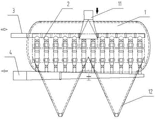
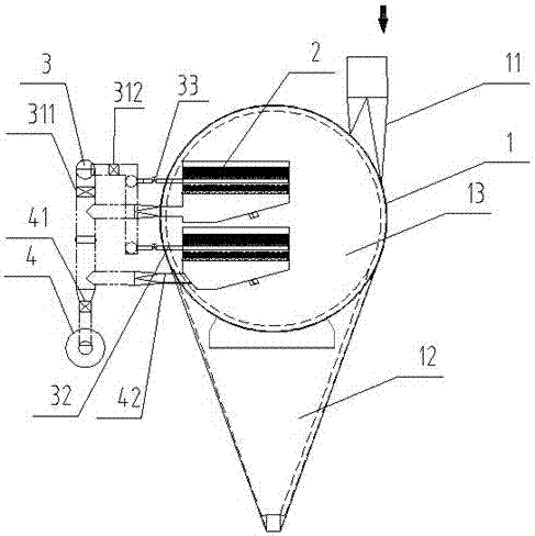
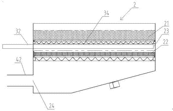
[0023] Such as Figure 1-3 As shown, a high-temperature dust collector includes a horizontal housing 1, several filter unit groups arranged in the housing 1, and an air induction manifold 4 and an anti-blow pipe 3 arranged outside the housing. The filter unit group is arranged along the lateral direction of the casing 1, and the filter unit group includes several filter units 2 arranged along the longitudinal direction of the casing. The casing 1 is provided with an air inlet 11, and the inside of the casing 1 is provided with a dust collection channel 13. The bottom of the casing 1 is provided with several dust outlets 12 along the transverse direction, the bottom of the filter unit 2 is provided with an air outlet 24, and the air outlet 24 is connected with a comprehensive air duct 42, and the reverse blowing duct 3 and the air guide The air confluence pipes 4 are all connected to the integrated air duct 42 and connected to the air outlet 24 through the integrated air duct 4...


PUM

PropertyMeasurementUnit
heightaaaaaaaaaa

Abstract

The invention discloses a high-temperature dust remover. The high-temperature dust remover comprises a horizontal housing (1), a plurality of filter unit sets arranged in the housing (1), and an induced air collecting pipe (4) and a blowback air pipe (3) arranged outside the housing. The filter unit sets are arranged along a lateral direction of the housing (1). The filter unit set comprises a plurality of filter units (2) arranged in the longitudinal direction of the housing. The housing (1) is provided with an air inlet (11). A dust collecting channel (13) is arranged in the housing (1). The bottom of the housing (1) is provided with multiple dust discharging openings (12) along the transverse direction. The bottom of the filter unit (2) is provided with an air outlet (24). The blowback air pipe (3) and the induced air collecting pipe (4) are connected to the air outlet (24) through an integrated air duct (42). The high-temperature dust remover has an ingenious structure, low total height of the device, good filtering effects, good backflushing cleaning effects, small temperature difference between upper and lower sides in the dust remover, and high safety.

Description

technical field [0001] The invention relates to the technical field of gas filtration and dust removal, in particular to a high-temperature dust collector used in coal chemical industry and flammable gas high-temperature separation process. Background technique [0002] In the field of dust removal technology, double-layer filter material particle bed dust removal has unique technical advantages. Two kinds of filter materials, coarse and fine, are used for filtration and placed on different filter bed structures of the same filter unit. In the bottom, filter through the filter bed to achieve a good filter and dust removal effect. In the prior art, the filter units in the dust collector are arranged vertically so that the height is too high, reaching more than 17 meters, and the dust collector is mostly used in areas with high wind force. In these areas, the required windproof infrastructure requirements are increased for every 1 meter of height increase. It will be much hig...

Claims


Application Information

Patent Timeline
Patent Type & Authority Applications(China)
IPC IPC(8): B01D46/30B01D46/00
CPCB01D46/30B01D46/62B01D46/72B01D46/71
Inventor 王兴云王筱吟任晓庆蒋协明
Owner 江阴远帆环保科技有限公司
Features
  • R&D
  • Intellectual Property
  • Life Sciences
  • Materials
  • Tech Scout
  • Unparalleled Data Quality
  • Higher Quality Content
  • 60% Fewer Hallucinations
Learn More